
MewPro Video Motion Detect board is ready for purchase. This automatically does start/stop recording on GoPro Hero 3+ Black. And here is two demos and a How-To.
Demo Videos
In order to experiment with video motion detect, preparation of the following items should be enough:
- 1. GoPro Hero 3+ Black
- Older GoPro’s doesn’t work with MewPro. (GoPro Hero 4 Black must be OK, but we don’t promise this.)
- 2. MewPro board
- SMD parts and Herobus connector are soldered.
Note: Don’t solder an Arduino Pro Mini to your MewPro board as its micro processor has not enough memory and is too slow to deal with video signal. - 3. Teensy 3.x or GR-KURUMI
- Our shop doesn’t sell these micro processor boards. Please purchase one of these items at somewhere.
- 4. MewPro VMD (Video Motion Detector) board
- Necessary SMD parts are soldered.
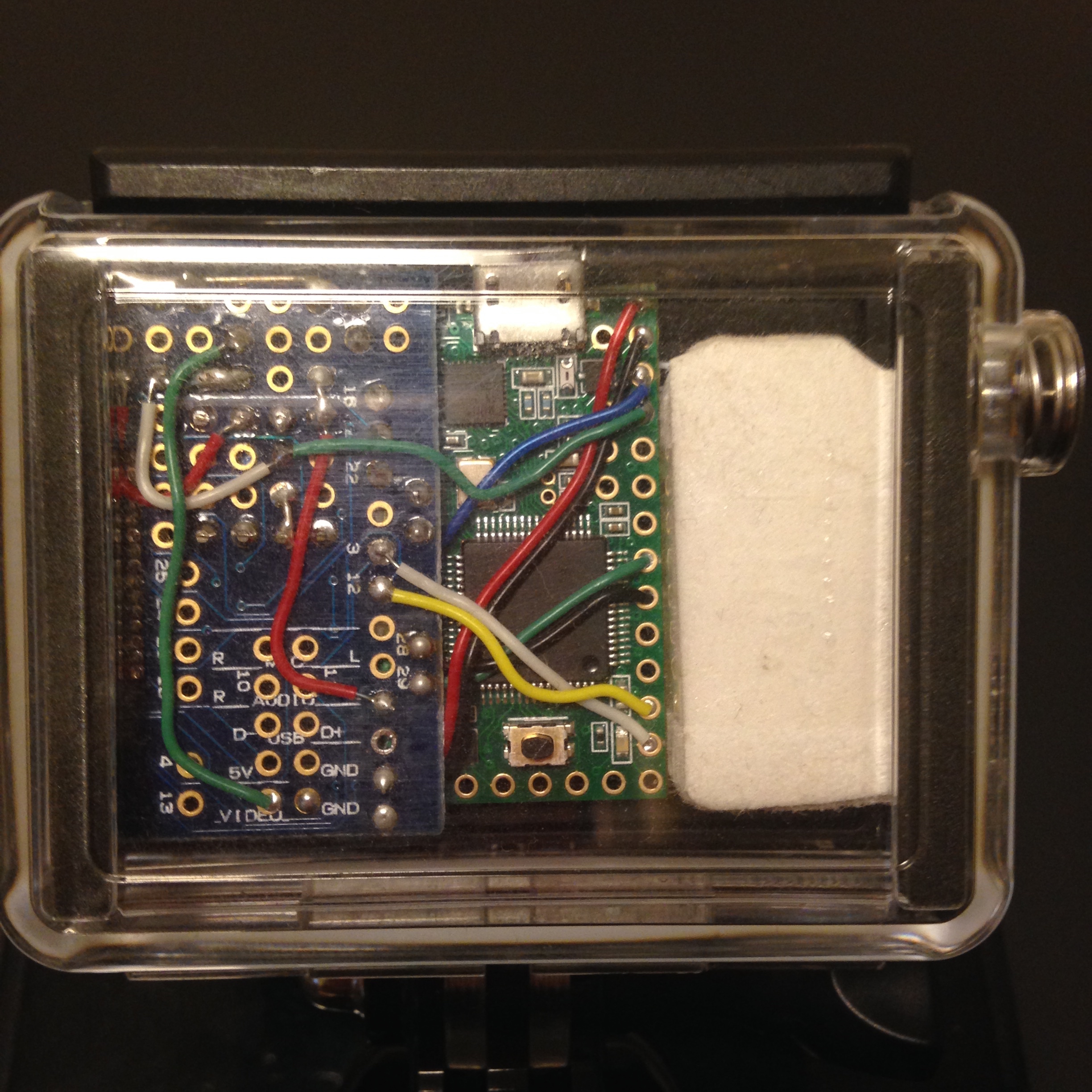
Three boards 2-4 (MewPro, Teensy 3.x or GR-KURUMI, and VMD) are soldered to form a BacPac™.
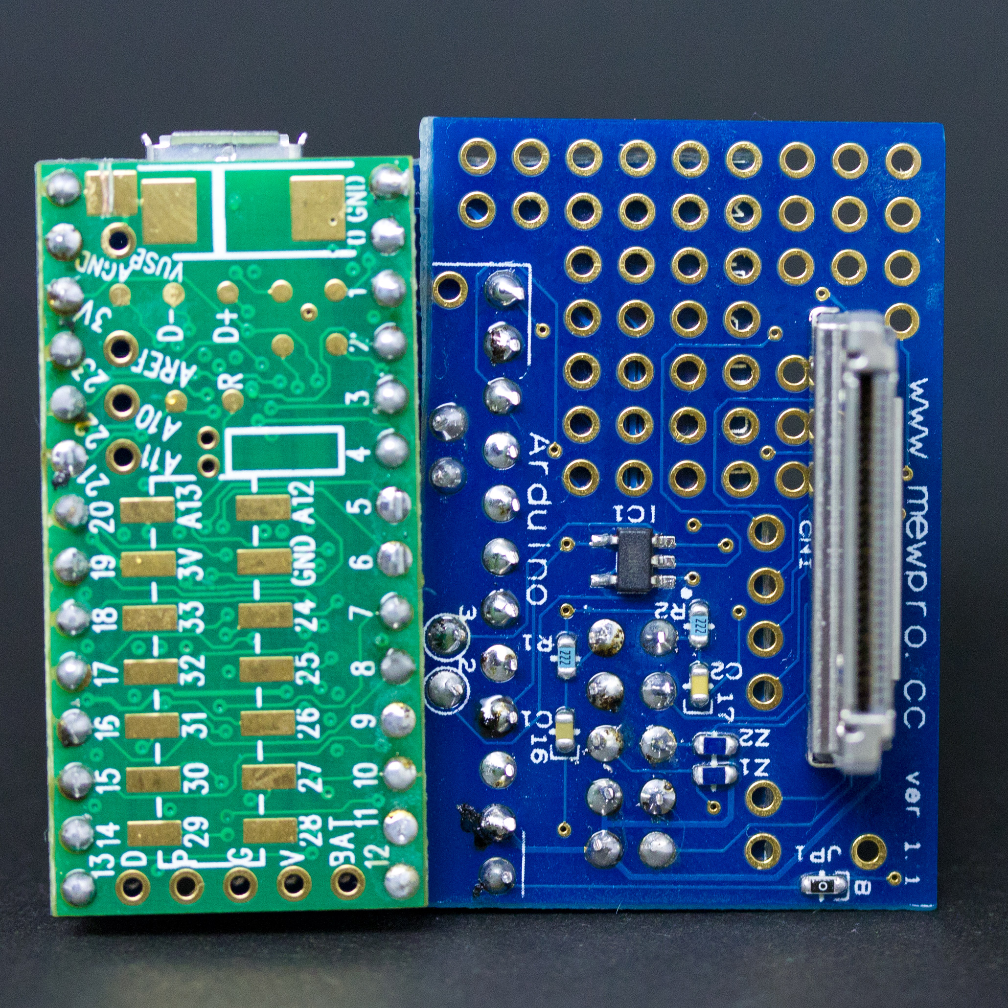
⇧ Teensy 3.1 w/ MewPro and VMD
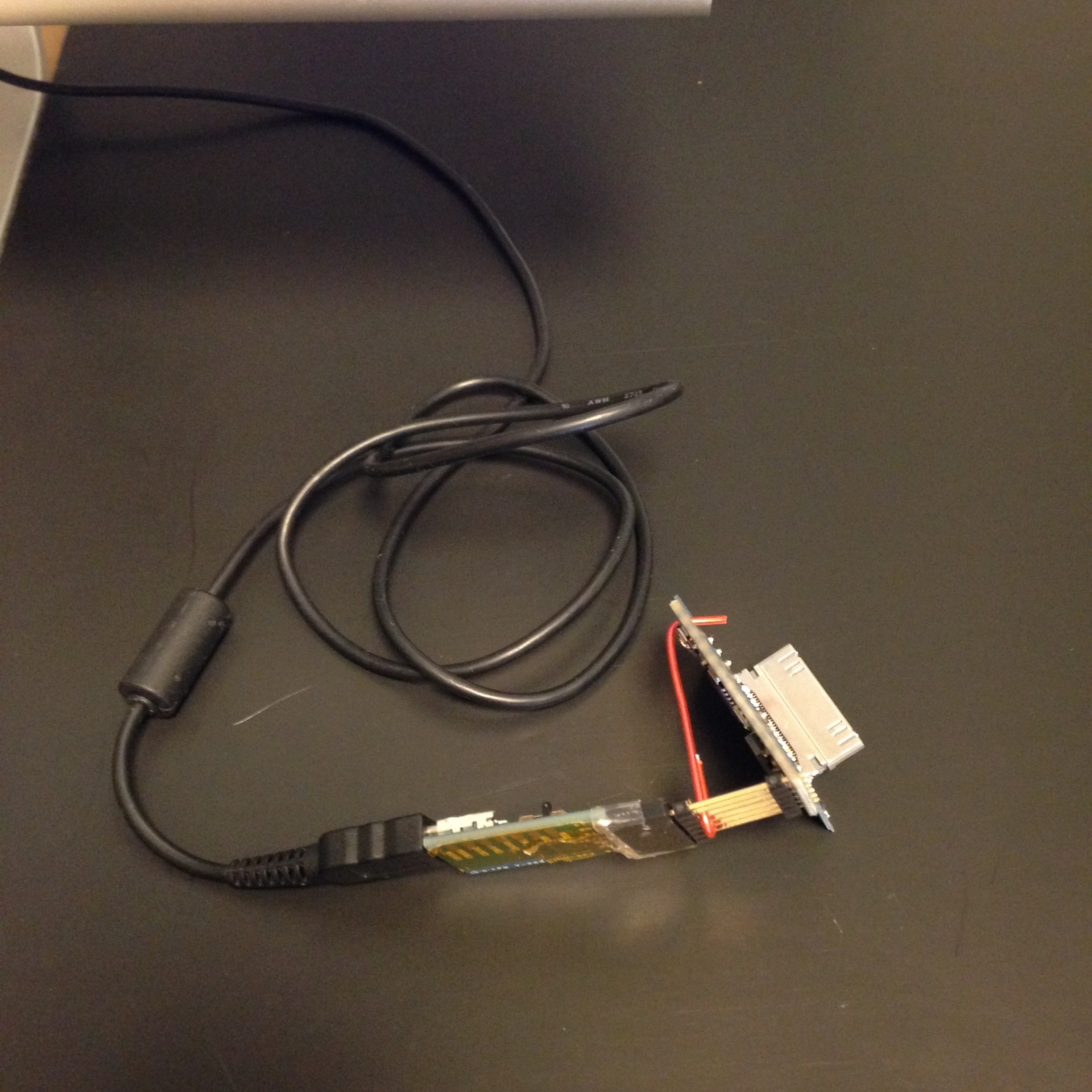
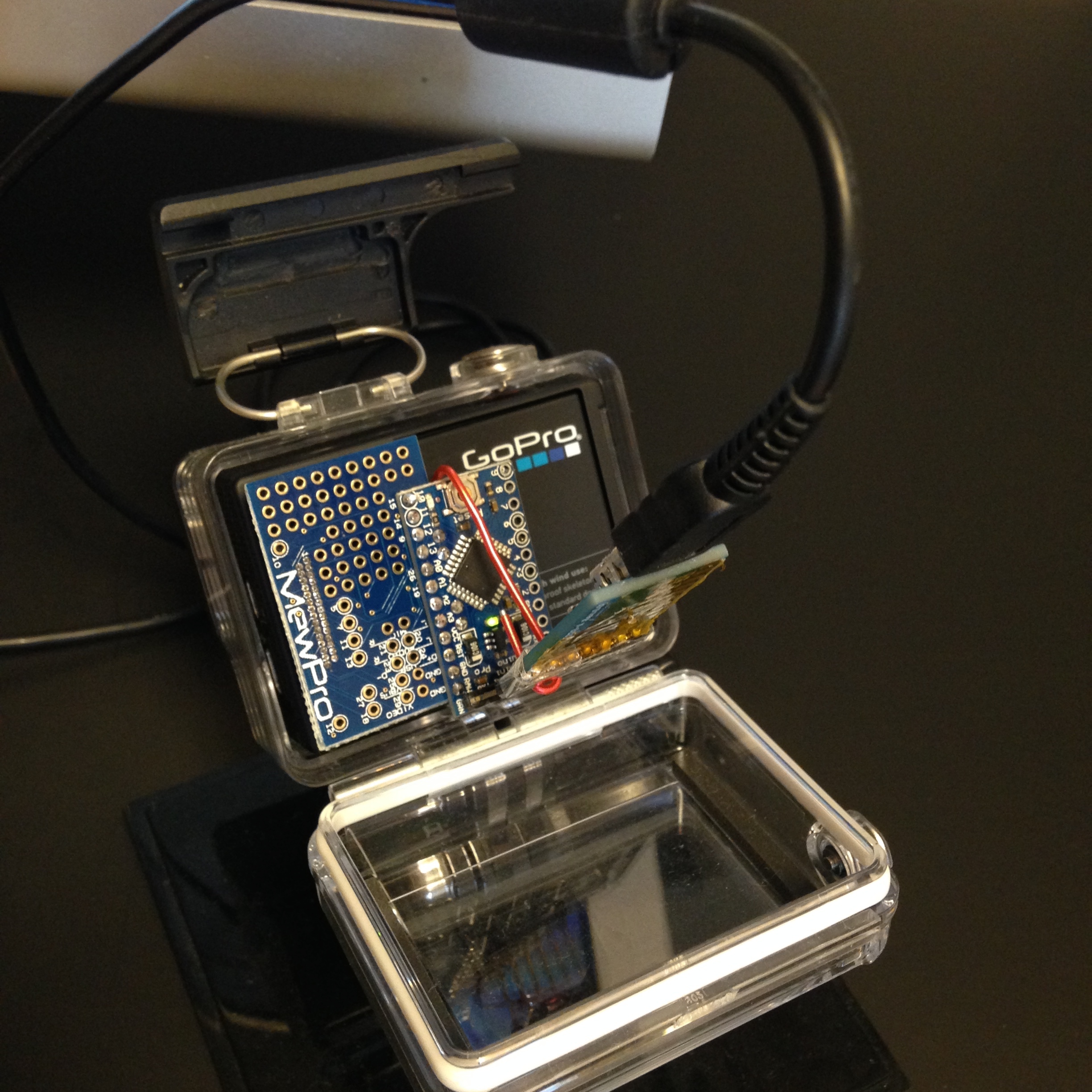
And the BacPac™ is attached to the Herobus receptacle.
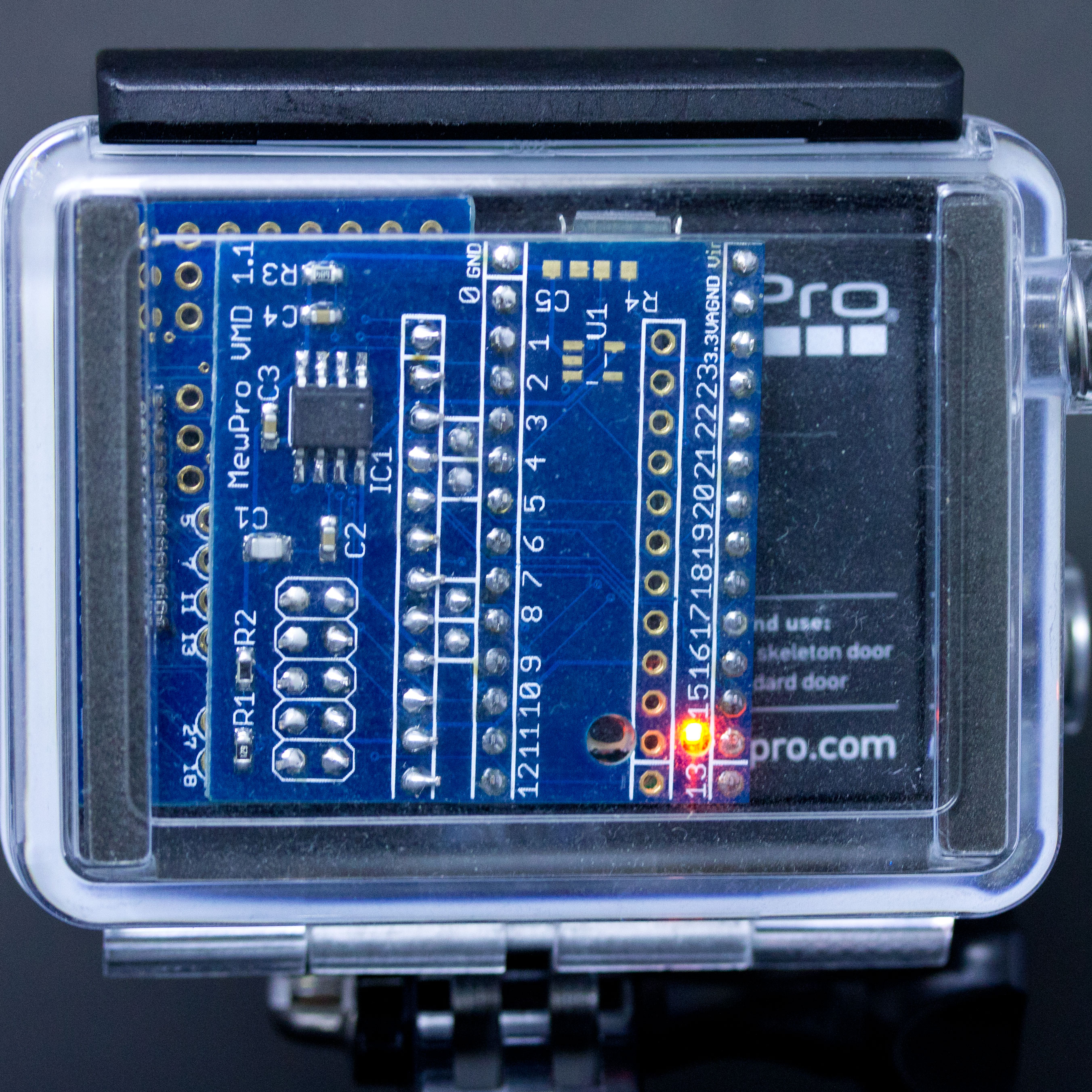
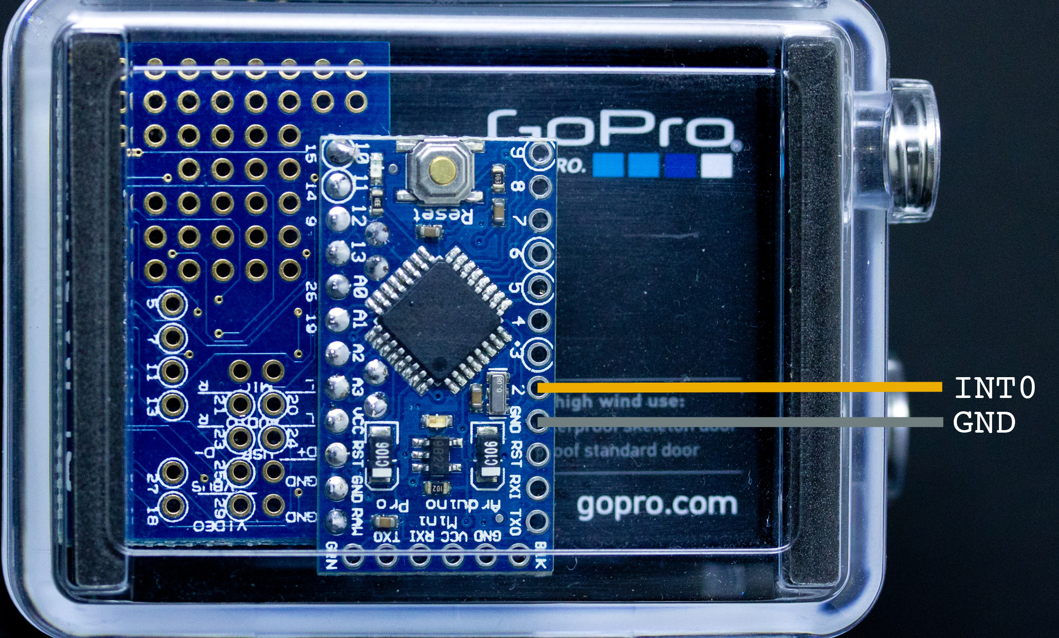
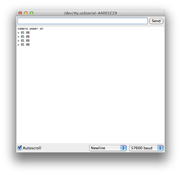
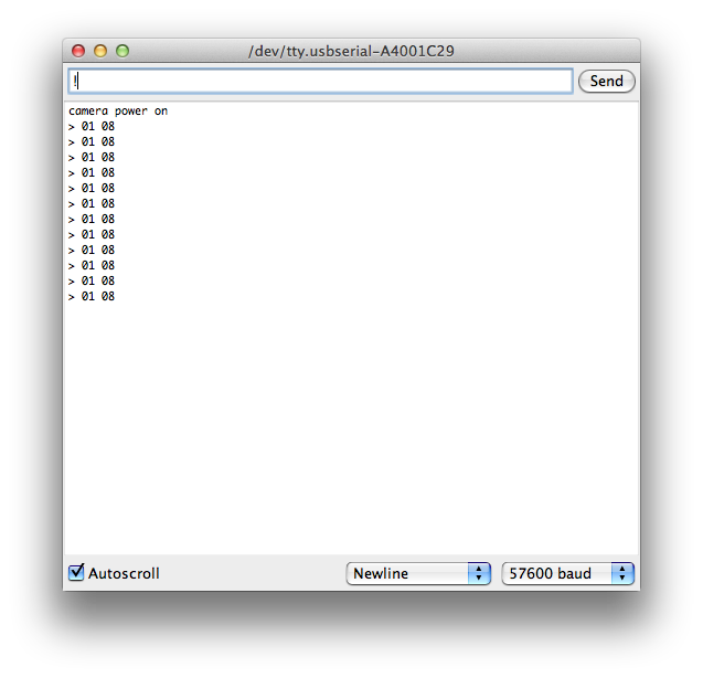
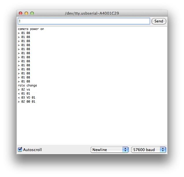
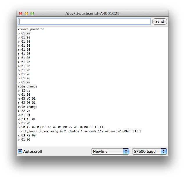
Using the BacPac™ is fairly simple: Place GoPro and push the power button on. After 5 seconds (or pre-configured period of time) the motion detect algorithm starts; the BacPac™ keeps a watch on the composite video signal on Herobus™. If it finds a movement then it commands GoPro to start recording video, and if no more changes then it orders the camera to stop and waits for another motion.
We made two demo video using MewPro (The Video Motion Detector BacPac™ appeared in the following makings of corresponding demo is the final prototype of the production version):
Video 1:
⇧ Auto captured video by a movement of kitty. No trim, No edit.
⇧ Making of Video 1 (captured manually by a human using iPhone 5c)
Video 2:
⇧ Video 2: Auto captured video by a movement of kitty. No trim, No edit.
⇧ Making of Video 2 (captured manually by a human using iPhone 5c)
How To Use MewPro Video Motion Detector Board
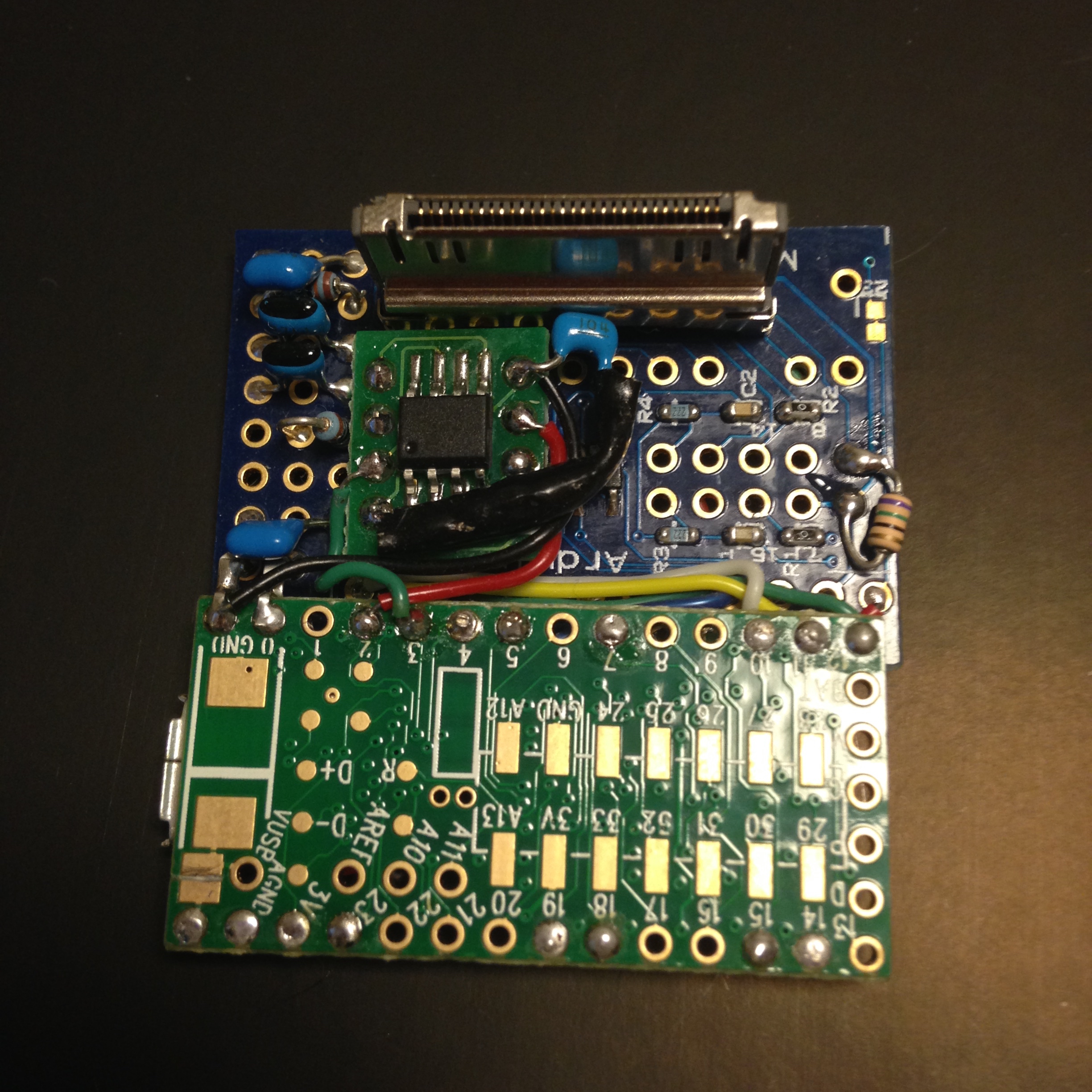
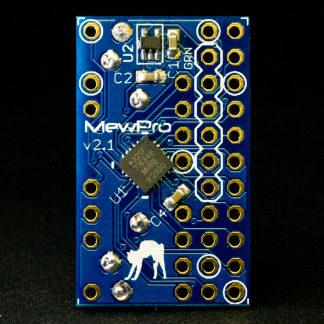
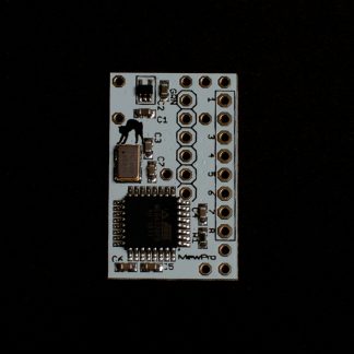
The following are the photos of MewPro VMD board w/ SMD parts soldered:
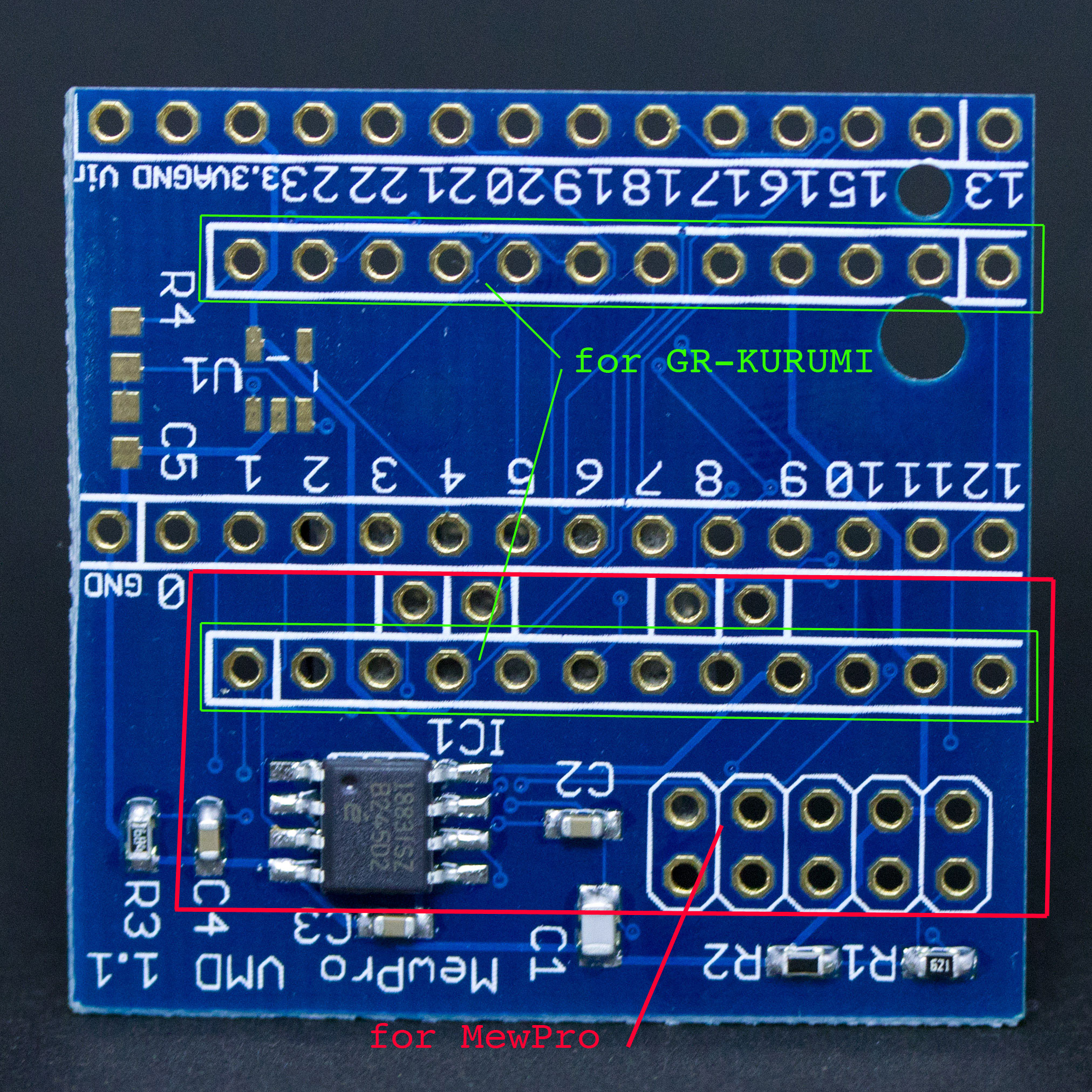
⇧ Top view
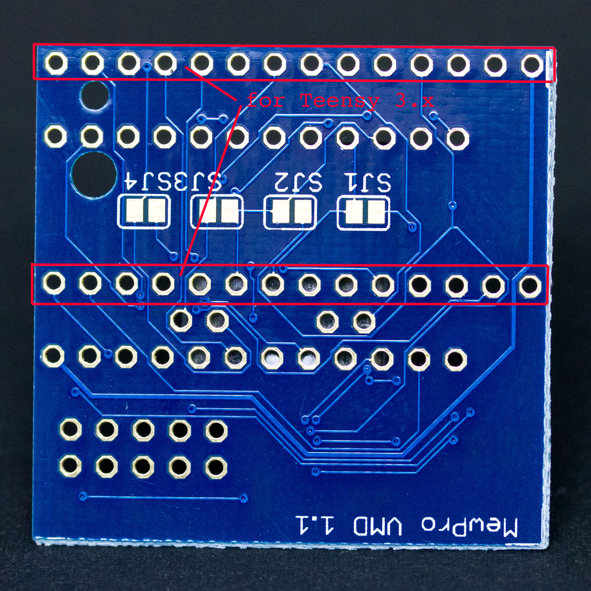
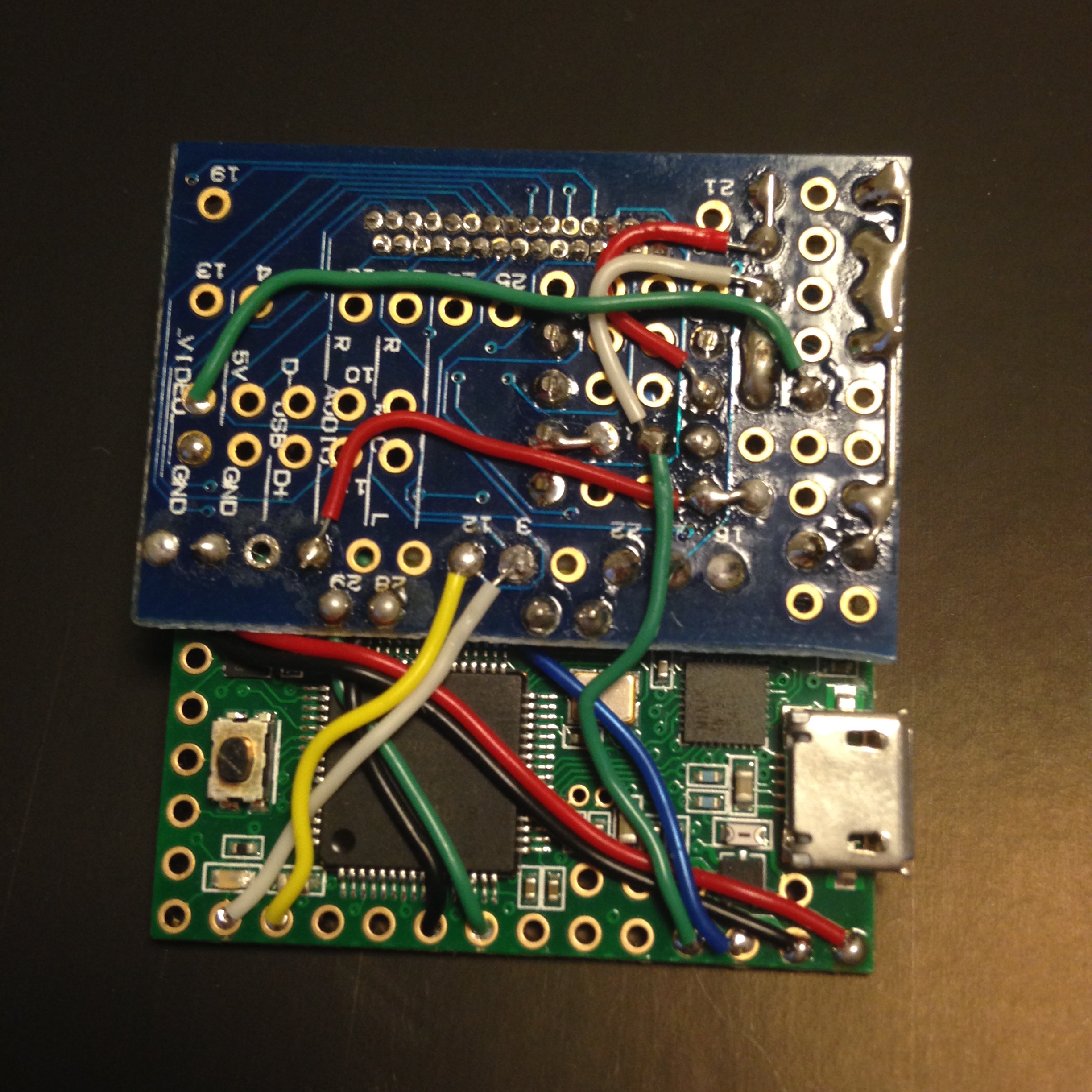
⇧ Bottom view
Three SMD parts (U1, R4, R5) need not to be mounted if the companion board is Teensy 3.x. Also if the companion board is GR-KURUMI then solder jumpers on SJ3 and SJ4 are necessary. Schematics of the board is here. Through holes look like 600mil 28pin DIP are for Teensy 3.x and the ones 600mil 24pin DIP are for GR-KURUMI and MewPro board.
We designed the VMD board so that Teensy is mounted on the bottom (i.e., front side of GoPro) and GR-KURUMI on the top (i.e., back side of GoPro). Please investigate the following photos carefully and solder the three boards in correct directions.
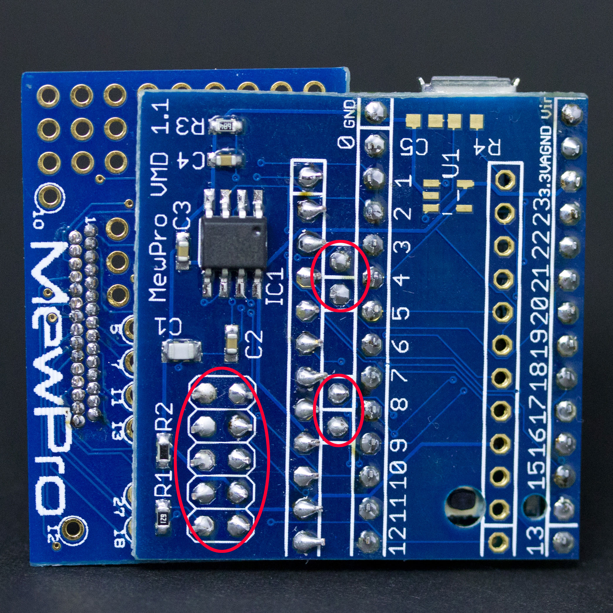
⇧ Teensy 3.x: View from GoPro back
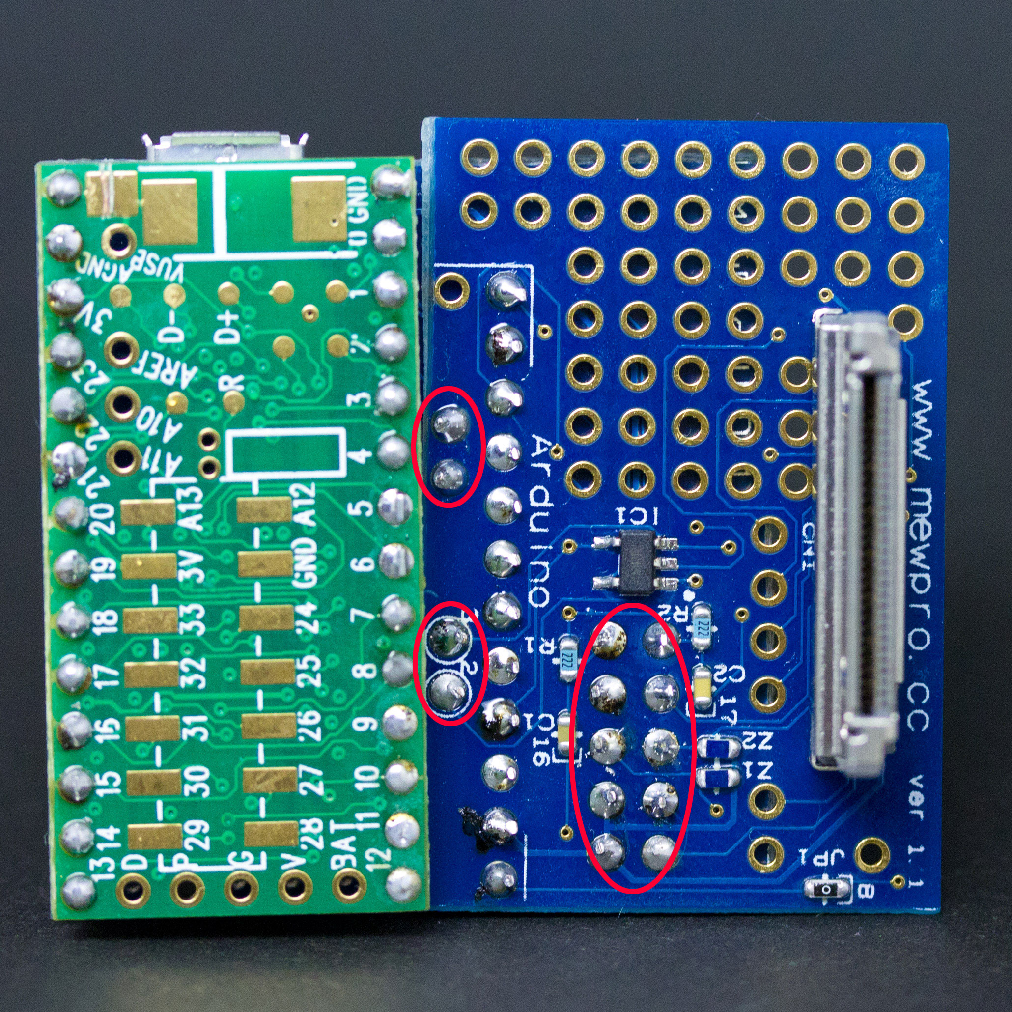
⇧ Teensy 3.x: View from GoPro front
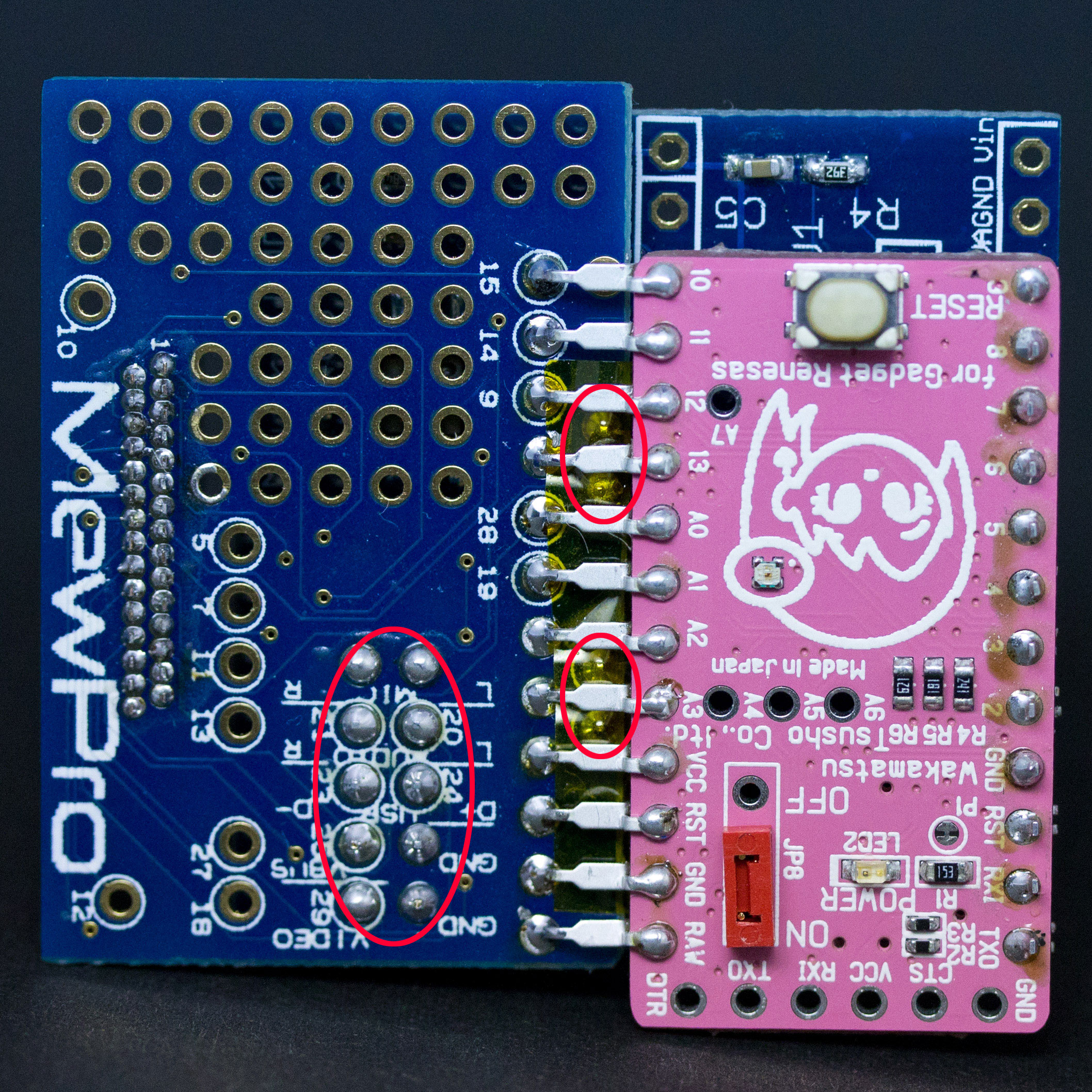
⇧ GR-KURUMI: View from GoPro back
Note: Please don’t forget to solder two pairs of two pins and 2×5 pins red-circled in the above photos.
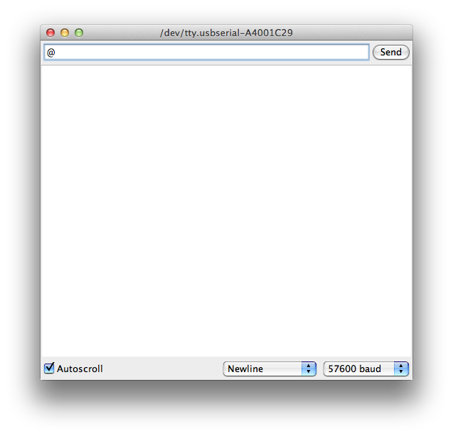
After soldering VMD board with Teensy or GR-KURUMI, and MewPro, connect it to PC and burn the MewPro application (To do so please refer the general instruction using MewPro).
In order to use VMD, it will suffice that the source code of MewPro application is modified at the following lines in MewPro.ino:
//********************************************************

// j_VideoMotionDetect: Video Motion Detector

//   Video motion detect consumes almost all the dynamic memory. So if you want to use this then #undef all options above.

#undef  USE_VIDEOMOTION

// The part of code utilizes the following library except GR-KURUMI. Please download and install:

//   https://github.com/orangkucing/analogComp

//#include "analogComp.h" // *** please comment out this line if USE_VIDEOMOTION is not defined or GR-KURUMI ***
And change the lines like this:
//********************************************************

// j_VideoMotionDetect: Video Motion Detector

//   Video motion detect consumes almost all the dynamic memory. So if you want to use this then #undef all options above.

#define USE_VIDEOMOTION

// The part of code utilizes the following library except GR-KURUMI. Please download and install:

//   https://github.com/orangkucing/analogComp

#include "analogComp.h" // *** please comment out this line if USE_VIDEOMOTION is not defined or GR-KURUMI ***
(If you are to use GR-KURUMI, keep the last line above untouched.)
Note. There are two threshold parameters of sensitivity in j_VideoMotionDetect.ino as well as some code fragments for debug. Please refer the comments written in the file.