Posted on Leave a comment

Status of Supporting Hero 4

Today we got a brand-new GoPro Hero 4 Black. However, currently MewPro doesn’t work with it.

We attached MewPro to it and investigated responses for I²C commands. It seems that the supporting module of Dual Hero System, which MewPro also relies on, has not yet implemented on Hero 4.

Someone on the Net has already asked GoPro about Dual Hero System compatibility on Hero 4, and the official answer from the company was “not yet”.

So please wait until they release a new firmware. We believe that if a camera works with Dual Hero System then MewPro can also work with the camera.

Update 10 Feb 2015: GoPro Hero4 Black (firmware 02.00.00) doesn’t support Dual Hero System yet.

Posted on Leave a comment

Telnet to GoPro Hero 3+ Black

The post is to explain how to log-in to the Linux console of Hero 3+ Black.

A real-time operating system (RTOS) is running on GoPros, and a Linux is also running as a task of the RTOS. For example, communication between Herobus and GoPro Hero 3+ Black is maintained by the RTOS and the web server (Cherokee), which GoPro apps on smart phones and/or Wi-Fi Remotes are to connect, is by the Linux.

There’s a well-known hack for telnet-ing to GoPros: Putting a tuned autoexec.ash file on the root directory of microSD card. But the hacks written for older GoPros don’t work for Hero 3+ Black. The issue is because Hero 3+ Black seems to lack some linux commands such as pkill or telnetd at a glance. But don’t worry. These commands are actually implemented by busybox, not by standalone binaries even for older GoPros.


Steps to telnet-ing to Hero 3+ Black

  1. Create a text file named autoexec.ash that contains the following lines:

    Note: Each end-of-line should be ‘\n’ (Unix style), not ‘\r\n’ (MSDOS style).
  2. Put the autoexec.ash file to the root directory of microSD card where DCIM and MISC reside.
  3. Insert the microSD into your Hero 3+ Black.
  4. Turn on Wi-Fi and enter “GoPro App mode” using the side button of camera body.
  5. Power on GoPro using the front button of camera body.
  6. Connect GoPro’s Wi-Fi from your PC or Mac.
  7. Wait about 30 seconds.
  8. Type telnet 10.5.5.9 8080 on your terminal.

Voilà! You can now enter to the Linux on GoPro Hero 3+ Black.
telnet
If you have memdump in the root directory of your microSD then you can dump RTOS log, too:
memdump
dump

Posted on Leave a comment

Utilize Unused Footprints on 5V LCD Modules

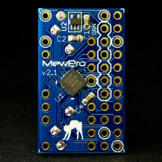
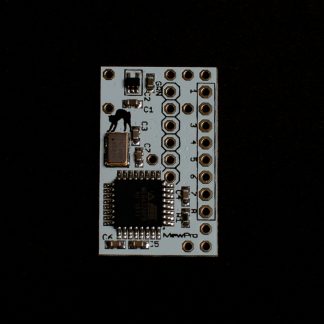
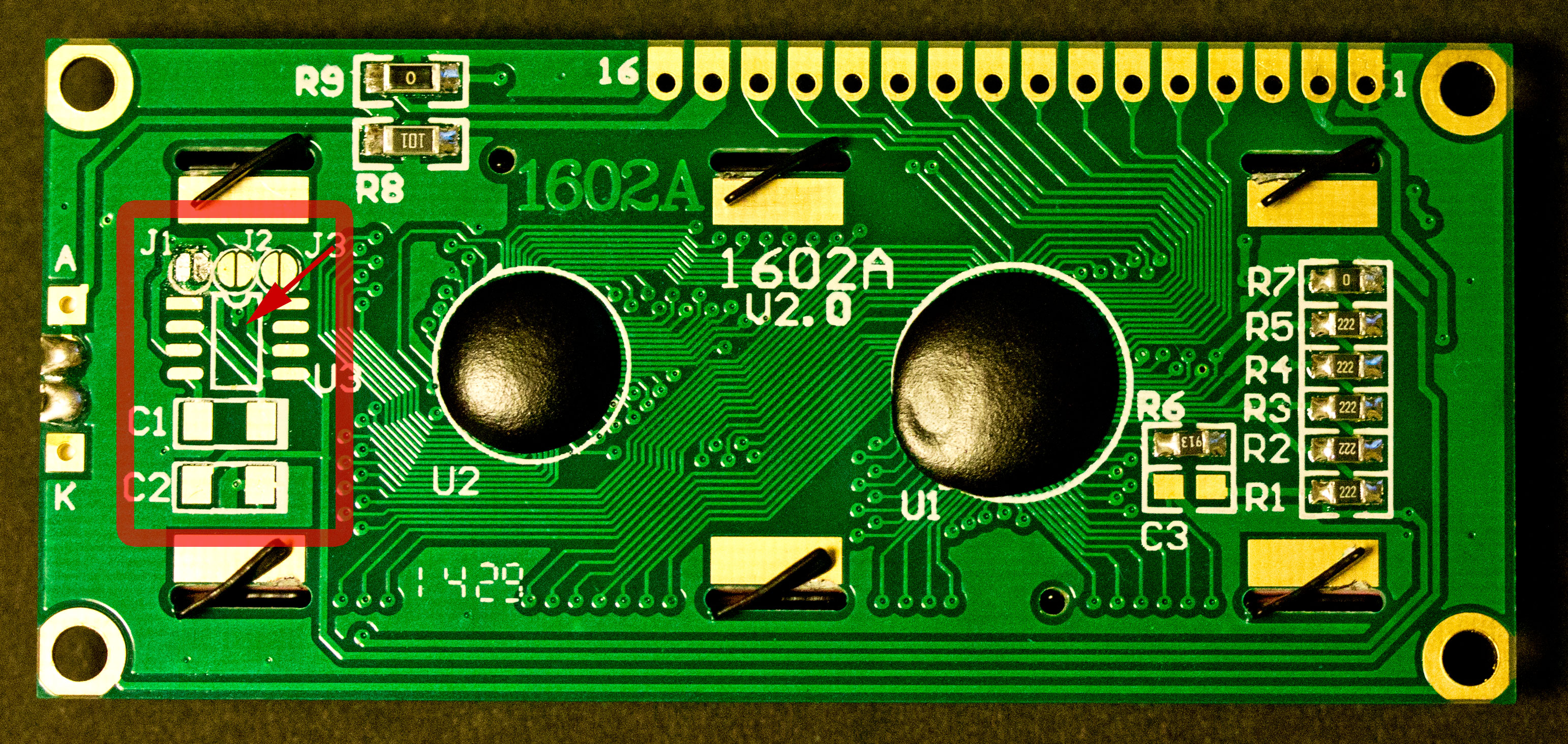
Some LCD modules have unpopulated footprints on the back (see Photos 1 and 2). Usually these pads are for ICL7660 (MAX660, MAX1044, or compatibles), a switched-capacitor voltage converter. This post is to attempt installation of MAX660 on dirt cheap 5V LCD modules and 3.3Vizing them.

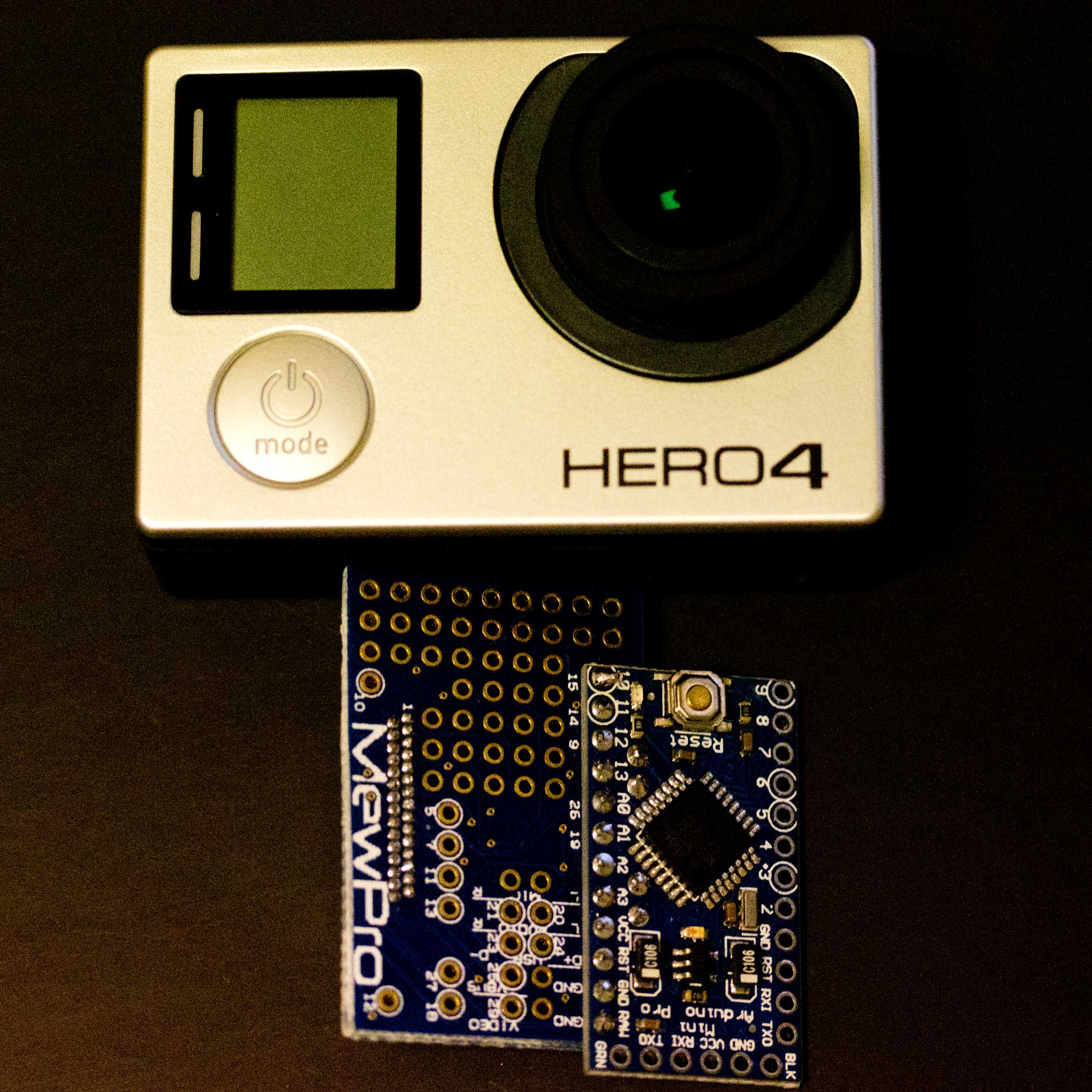
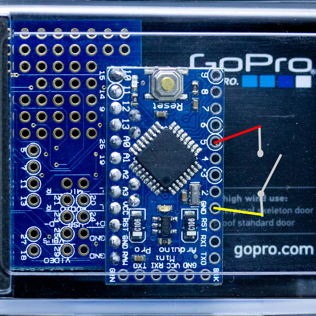
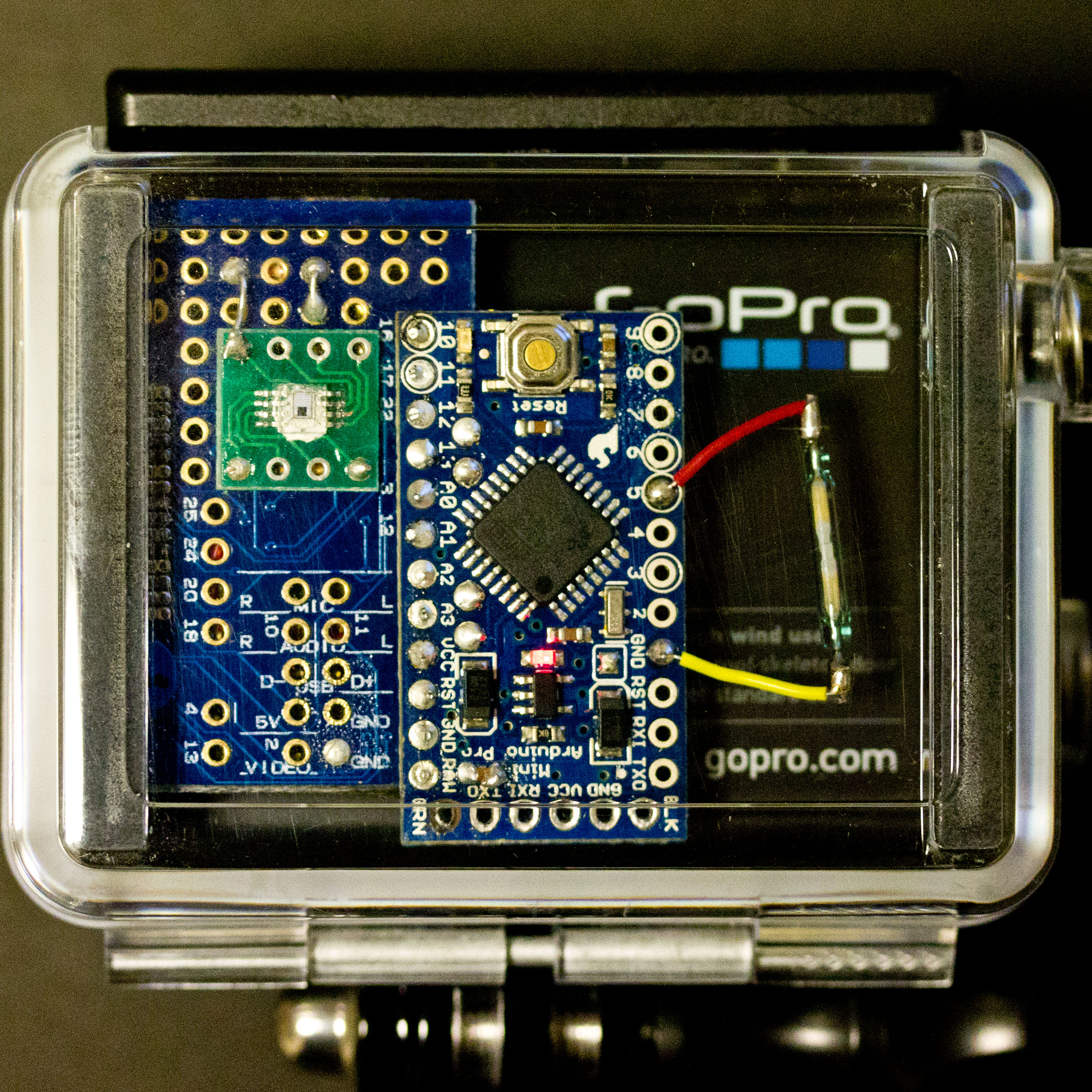
Note: The article is nothing to do with GoPro. This is related to our another project “NFC tags for schools”. A summary of the product will be shown at the end of post.

1602A-b
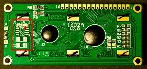
⇧ Photo 1: HJ1602A, Shen Zhen Huijing Technology Co., Ltd (cn: 深圳绘晶科技有限公司) [395JPY at Aitendo, Tokyo, Japan]

0820-b
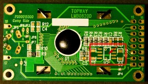
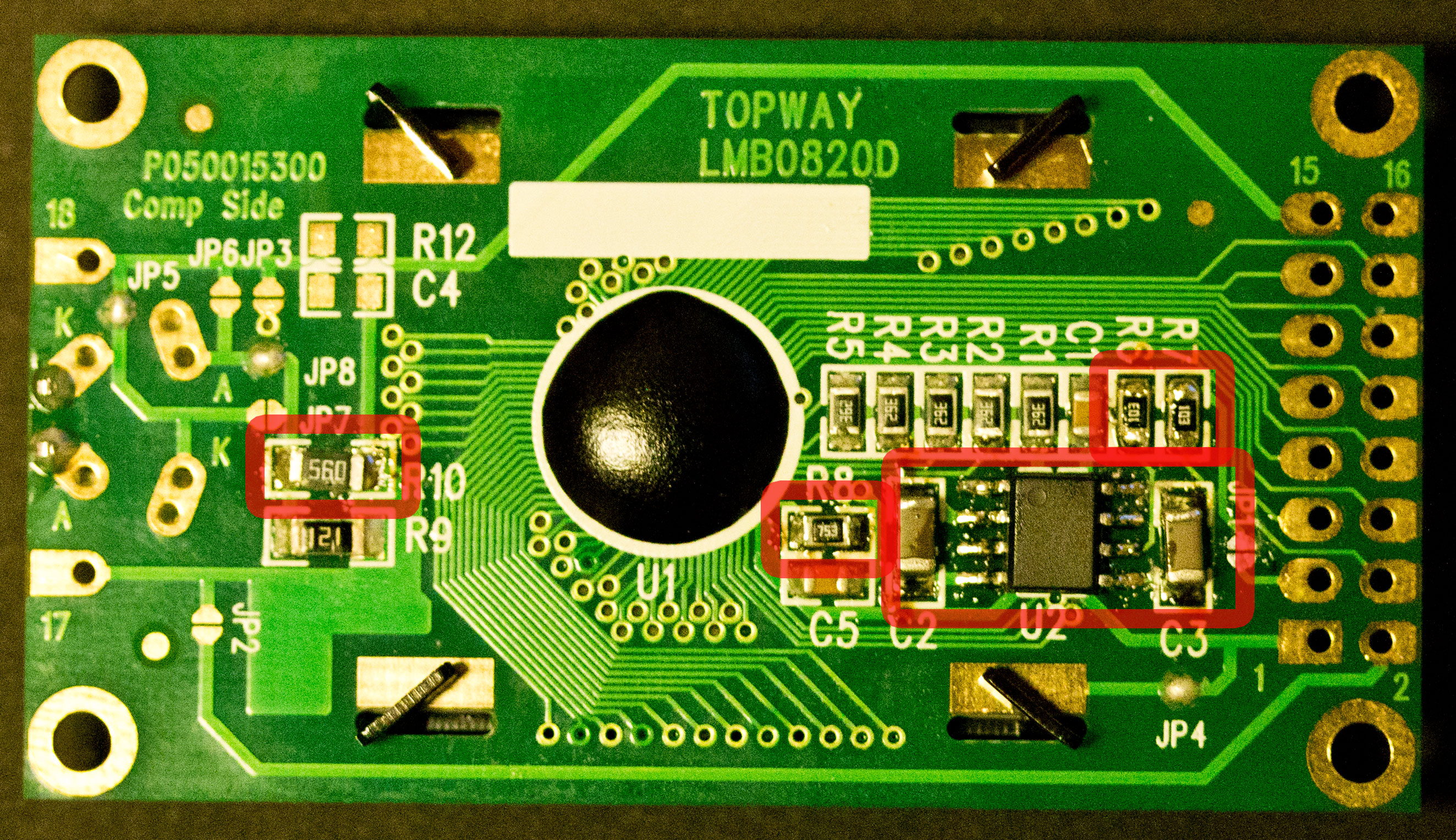
⇧ Photo 2: Seed Studio LCD104B6B or TOPWAY LMB0820D [570JPY at Sengoku Densyo (ja:千石電商), Tokyo, Japan]

1. Why 3.3V?

These days many devices are working on 3.3V or even on 1.8V, for example, GoPro is on 3.3V, and Intel Edison is on 1.8V. However, liquid crystal displays (LCDs) are usually on 5V, because they are made out of 1980s’ technology due to Hitachi’s de facto standard LCD controller chip HD44780.

Thus there are many sites explaining 3.3Vizing of LCDs, for example,

The latter author did a very similar thing to the current article (i.e., he mounted ICL7660 to another LCD). So I’m afraid this post might be a kind of “reinventing the wheel”, but writing this now because it might be useful to someone especially who can actually go and buy these LCDs in Tokyo.

2. Experiment

It seems that HJ1602A (Photo 1) is sometimes sold with ICL7660 mounted. Fortunately we can find such a photo at Magyar site (see “6_2. ábra”). So the LCD is very easy to 3.3Vize as in the following picture:
1602A-a
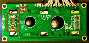
⇧ Photo 1′: Mounting MAX660 to 3.3Vize HJ1602A

Note: U3=MAX660, C1=C2=10uF, J1=J2=open, J3=close, R8=330 (R8 for back light current restriction at 3.3V)

For LMB0820D (Photo 2) we haven’t yet found any picture on the Net with ICL7660 mounted. But we have already learned how to mod it from two examples above:
0820-a
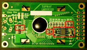
⇧ Photo 2′: Mounting MAX660 to 3.3Vize LMB0820D

Note: U2=MAX660, C2=C3=10uF, R6=R7=10k, R8=75k, R10=560 (R10 for back light current restriction at 3.3V), JP5=JP8=close (for enabling back light)

3. Results

Here are the results of mods:
1602A-u
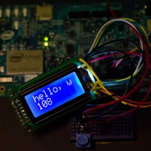
⇧ Photo 1″: HJ1602A at 3.3V

0820-u
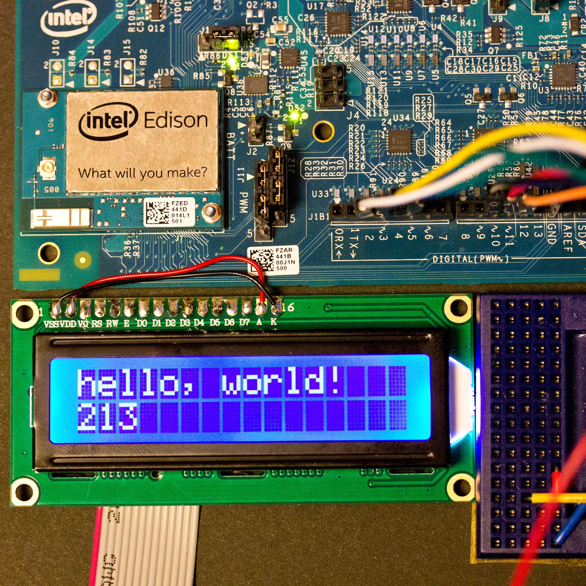
⇧ Photo 2″: LMB0820D at 3.3V

These are worked on Intel Edison Arduino Board set 3.3V and/or Intel Edison Breakout Board with FXLA108, a dual-supply 8-bit signal translator.


PR: NFC tags for schools

At the beginning of the current project we like to vet some usable LCDs for our purpose: an electrical roll book for schools. The roll book device is required to be able to:

  • Communicate with Google Spreadsheet through 5GHz Wi-Fi network (for uploading attendance/absence records and downloading the list of registered students)
  • Read NFC tags embedded in student ID cards
  • Show results instantly while scanning an ID

Aiming these we have decided to use Intel Edisons for the CPU and Sony RC-S380 for the card reader. And then we came to choose one more item, some brand of low cost LCD works on 3.3V.

edison
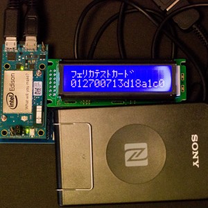
⇧ Prototype of our Electrical Roll Book Device: Intel Edison (left), 3.3V LCD (right), Sony NFC reader (bottom)

This device is nearly completed by now, and one unit of system is fixed to be delivered to a collage in Shizuoka, Japan.

Posted on Leave a comment

You Like Underwater Selfie?

Adding a programmable switch to MewPro helps us, for example, to take selfies underwater.

No one is eager to drill a hole in underwater housing. But sometimes you might dream if there were an extra switch for customizable functions in GoPro then some great photo/video of something great (or GPOY) could be shot.

In this post, a method to use a reed switch and a magnet with MewPro is addressed. No drilling into housing will be required.

Parts List

  1. MewPro system (GoPro Hero 3+ Black, MewPro, Arduino Pro Mini)
  2. reed switch
  3. magnet
  4. (bits of solder and wires)

reed-switch-and-magnet
⇧ center: reed switch (cost about 2USD), right: neodym magnet (cost less than a dime)

The reed switch will be closed when magnet field is applied. The neodym magnet has strong enough force even from the outside of housing.

Wiring is simple as the following figure:
reed-schematic
⇧ connect D5 and GND pins to either leads of the reed switch

WARNING: Reed switches are very fragile; contacts are sealed in a thin glass envelop. Don’t bend the leads of switch or you will easily destroy/crack the glass.

reed-soldered
⇧ electrical wires are twisted around the straight leads before they are soldered

reed-sw-back
⇧ reed switch w/ a prototype of MewPro in GoPro housing


MewPro Software Mods

In MewPro.ino find the lines

//********************************************************
// f_Switches: One or two mechanical switches
#undef  USE_SWITCHES 

and modify them to

//********************************************************
// f_Switches: One or two mechanical switches
#define USE_SWITCHES

This will enable the part of code in f_Switch.ino:

void switchClosedCommand(int state)
{
  switch (state) {
    case (1 << 0): // SWITCH0_PIN
      if (!ledState) {
        startRecording();
      } else {
        stopRecording();
      }
      break;
    case (1 << 1): // SWITCH1_PIN
      startRecording();
      break;
    default:
      break;
  }
}

The statements in case (1 << 0) are executed when SWITCH0_PIN (= D5 as defined in MewPro.h) becomes the GND level, that is, when the neodym magnet gets near enough to the reed switch. The code above does simple things: start recording in video mode (or release the shutter in still camera mode) at the first time it is called, and at the second time stop recording (or no operation in still mode).

If you change the part of code anything can be accomplished. For example, modifying or adding a line of delay(10000); before startRecording();

void switchClosedCommand(int state)
{
  switch (state) {
    case (1 << 0): // SWITCH0_PIN
      if (!ledState) {
        delay(10000);
        startRecording();
      } else {
        stopRecording();
      }
      break;
    case (1 << 1): // SWITCH1_PIN
      startRecording();
      break;
    default:
      break;
  }
}

enables self timer of 10000 milliseconds (= 10 seconds) in still camera mode. Note this self timer mode is usable also in underwater where Wi-Fi is not available.