Posted on Leave a comment

PCB for Video Motion Detector Arrived

A MewPro add-on board “Video Motion Detector Board” will be ready soon; the PCBs have arrived to our lab.

We are now checking the functionalities of the board. So please wait two or three days more…

teensyVMD-top
⇧ Video Motion Detector w/ Teensy 3.1, back view

teensyVMD-back
⇧ w/ Teensy 3.1, front view (Reset button can be pushed through the hole, LED is visible)

kurumiVMD-back
⇧ w/ GR-KURUMI

Posted on Leave a comment

Teensy 3.x w/ MewPro and Motion Detection

More detailed articles will be published soon in this blog. Since there was a request for information about GoPro motion detection, I’m writing this very quickly.


Materials
The following hardwares and softwares I used.

  1. GoPro Hero 3+ Black
  2. MewPro board + MewPro application
  3. Teensy 3.1
  4. EL1883 sync separator
  5. Schematic to connect Teensy 3.1 and EL1883 w/ MewPro

IMG_5976
⇧ Motion Detect BacPac Side A: EL1883 (center left), Teensy 3.1 (bottom), and GoPro Herobus connector (top)

IMG_5975
⇧ Motion Detect BacPac Side B: MewPro board (trial product version) and Teensy 3.1

IMG_5977
⇧ Motion Detect BacPac fits into GoPro housing


Motion Detection
Basic ideas came from nootropic design Video Experimenter shield. They used LM1881 and the analog comparator of Atmel processor. I did almost the same thing using GoPro, EL1883 and the analog comparator of Teensy 3.1 (The most difficult part was to control GoPro from Herobus). Composite video signal is captured as binary frames (i.e., intensity is compared at the analog comparator in Teensy, if it is greater than the fixed threshold record 1, otherwise 0). In this way bit rate attained is 1 pixel/microsecond.

The following is a video capture of Serial Monitor connected to Teensy, showing debugging info: Powering on GoPro (by using MewPro ‘@’ command), initializing GoPro to output composite video (by using I2C command “VO”), and captured image output for debugging purposes. Actual capture is done every time the comparator interrupt (on both rising and falling edges) occurs; in the interrupt handler, the comparator output at that moment is also considered and if the comparator output is 1 then we record two bits of “01” (rising edge) otherwise “10” (falling edge); in the debug output even and odd frames are added (that’s why we sometimes notice the digit “2” while watching the following video).

Current motion detection algorithm implemented in MewPro application is very simple: Compare the pixels of adjacent frames; if the difference is large then something has moved.


Product PCB will be available within next week, and you will be able to buy it. Some more video demos are coming, too. So stay tuned.

Posted on Leave a comment

Yet another 3.3Vizing an Arduino

In this post we present some suggestion, “overclocking” on 3.3V and 16MHz Arduinos.

Processors from Atmel are usable on both 5V and 3.3V logics. For example, ATmega328P on Arduino Pro Mini or ATmega32U4 on Arduino Leonardo (Arduino Pro Micro) can work on both voltages without problems. But only one consideration is remained: 16MHz clock is not OFFICIALLY supported by Atmel if the processor is on 3.3V. So if you use these processors at 3.3V AND 16MHz you must understand/agree you are in danger(!) of overclocked them. (However, in many cases it should be safe and no problem.)

In this post we’ll do two overclocking experiments:

  1. Arduino Pro Mini 328 5V 16MHz → 3.3V 16MHz
  2. Arduino Leonardo (5V 16MHz) → (3.3V 16MHz)

1. Making Arduino Pro Mini 328 3.3V 16MHz
If you want Arduino Pro Mini 328 3.3V “16MHz” then there might be another way: Buy a genuine Arduino Pro Mini 328 3.3V “8MHz” and change the crystal (CERALOC® = ceramic resonator) on it. The problem is NO COMPATIBLE CERALOC® exists for the original one (original part no. is Murata CSTCE8M00G55A-R0). To be more precise, Murata makes a similar CERALOC® of 16MHz (part no. Murata CSTCE16M0V53-R0) but their footprints differ and 16MHz version can’t fit to the 8MHz place. So this method to change the crystal is not so easy to go through.

Thus we try the other way: Buy a genuine Arduino Pro Mini 328 “5V” 16MHz and change the voltage regulator on it. Photo: The location of regulator is marked red. The original voltage regulator is Micrel MIC5205-3.3YM5. It is the LoHS version of Micrel MIC5205-3.3BM5 and the footprint is SOT-23-5.

mini
(Sorry. I forgot to take a picture of original Arduino Pro Mini 328 5V 16MHz. The voltage regulator in this photo has already replaced by a 3.3V regulator.)

I used some low temperature solder (Removal Alloy by CHIPQUIK®) and two soldering irons to remove the SMD regulator. Detailed instruction of removing SMD parts is there in CHIPQUIK® site.

The replacement part should be any 3.3V voltage regulator that holds certain conditions. If you happen to get a Micrel MIC5205-3.3YM5 (LoHS) or Micrel MIC5205-3.3BM5 (non-LoHS) then you are very lucky to use the best one. However, the required conditions are, I think, only “3.3V fixed voltage”, “low dropout”, “150mA”, and “SOT-23-5” so there are many choices in buying a compatible regulator.

I used a Toshiba TAR5SB33 for the replace, because it is already there just in my parts-box. Soldering a SOT-23-5 part is not so difficult and is fun!

After soldering, connect the Arduino to your PC and check how it works (Don’t forget to use 3.3V version of FTDI board!!). In Arduino IDE, [Tools]→[Board] should be “Arduino Pro or Pro Mini” and [Tools]→[Processor] should be “ATmega328 (5V, 16MHz)” (Note: Arduino IDE doesn’t care about the voltage).


2. Making Arduino Leonardo (3.3V 16MHz)
There is a great article by Tyler Cooper on replacing Arduino Uno’s regulator to a 3.3V version. Arduino Uno and Leonardo are nearly identical around the power circuit (you can compare their schematics: Uno, Leonardo) so we could do the same on Leonardo, too.

However, the method Cooper used for Uno is not good for Leonardo who can speak some of USB protocols. Because after his surgery of removing the fuse XUSB signal doesn’t reach Uno’s (or Leonardo’s) processor pin but nowhere. USB 2.0 protocol requires XUSB (= VUSB) line to be alive (for checking impedances to D+/D-) at least speed negotiation phase thus the line shouldn’t be remained at infinite impedance or open after the surgery.

So I didn’t remove the fuse but did remove the MOSFET (T1 FDN340P in the schematic) marked red in the following photo.

leo
(Sorry, again. I also forgot to take a photo before removing/replacing something. In this photo the MOSFET has already removed, the voltage regulator replaced, and the additional diode attached.)

The rest of the surgery is the same as Cooper’s method: Replace the voltage regulator to a 3.3V version and connect VUSB to voltage regulator’s input pin through a diode. I used Advanced Analog Circuits AZ1086H-3.3 (SOT-223 package) for voltage regulator and 1N4007 for diode, however, any similar ones will do.

After removal and soldering things, connect the Arduino to your PC and check how it works. In Arduino IDE, no changes in settings are required (i.e., [Board] is also “Arduino Leonardo” and that’s all).


Enjoy!

Posted on Leave a comment

How To Use MewPro and Its Application

We will show you how to use a first time MewPro. Basics to control GoPro camera will be explained. No external sensors involved (Maybe in following posts, we can show you some examples of sensor usages).


Prerequisites

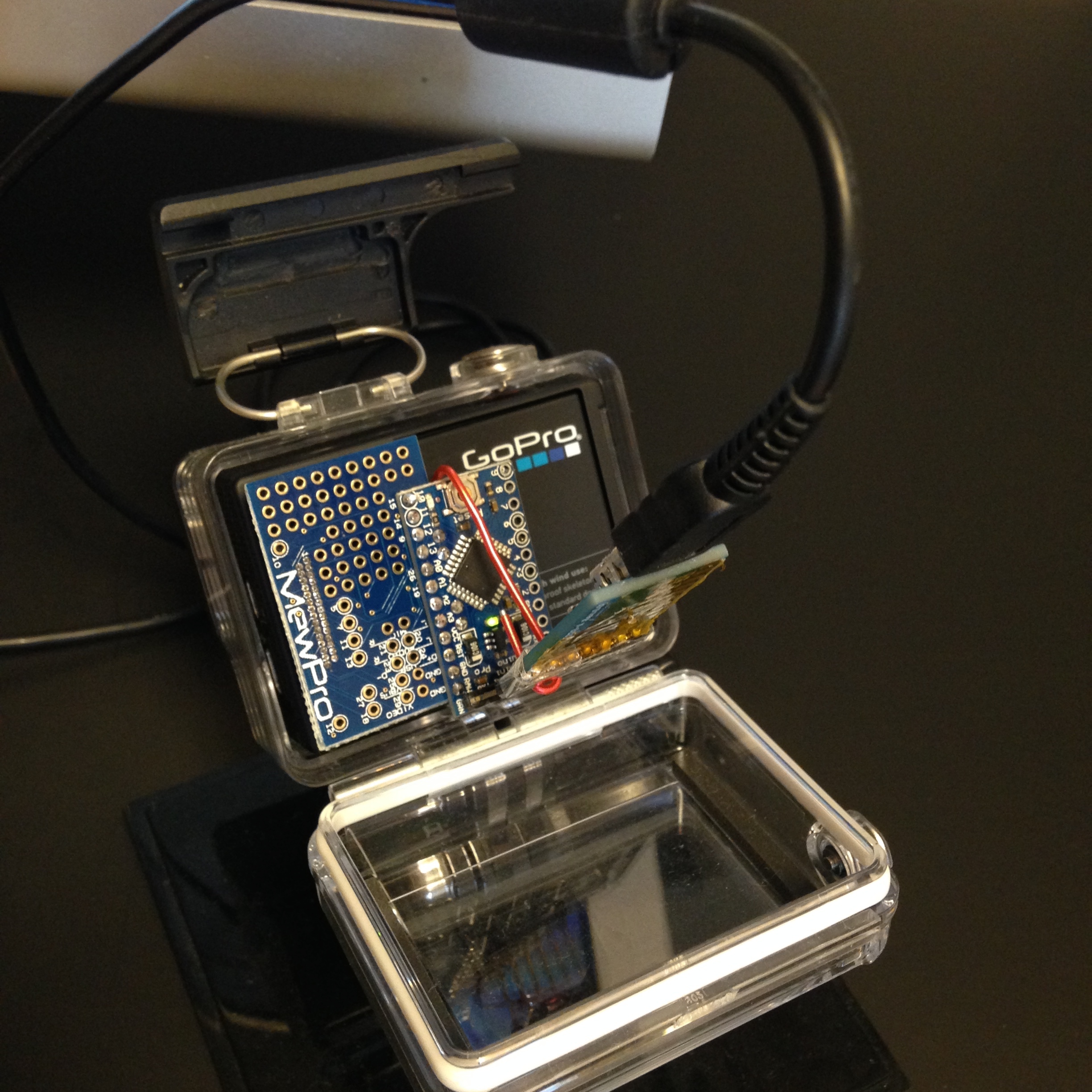
In order to use MewPro as a GoPro controller you need the following hardwares:

GoPro Hero 3+ Black
Neither previous editions nor Hero 3+ Silver work with MewPro. Hero 4 Black will be expectedly supported but we don’t promise this. (Update: Hero 4 Black/Silver are supported by MewPro 2/Cable. Please refer recent posts for them.)
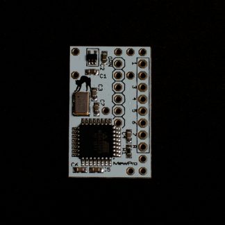
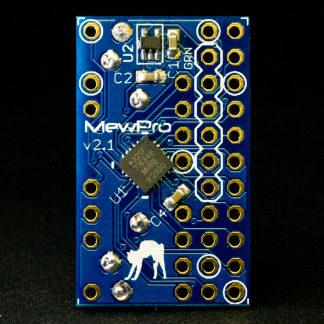
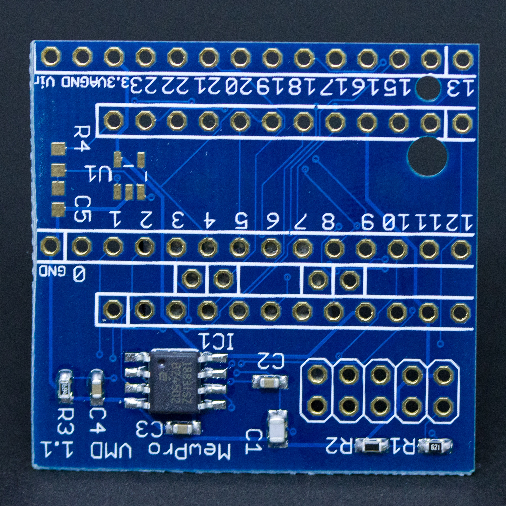
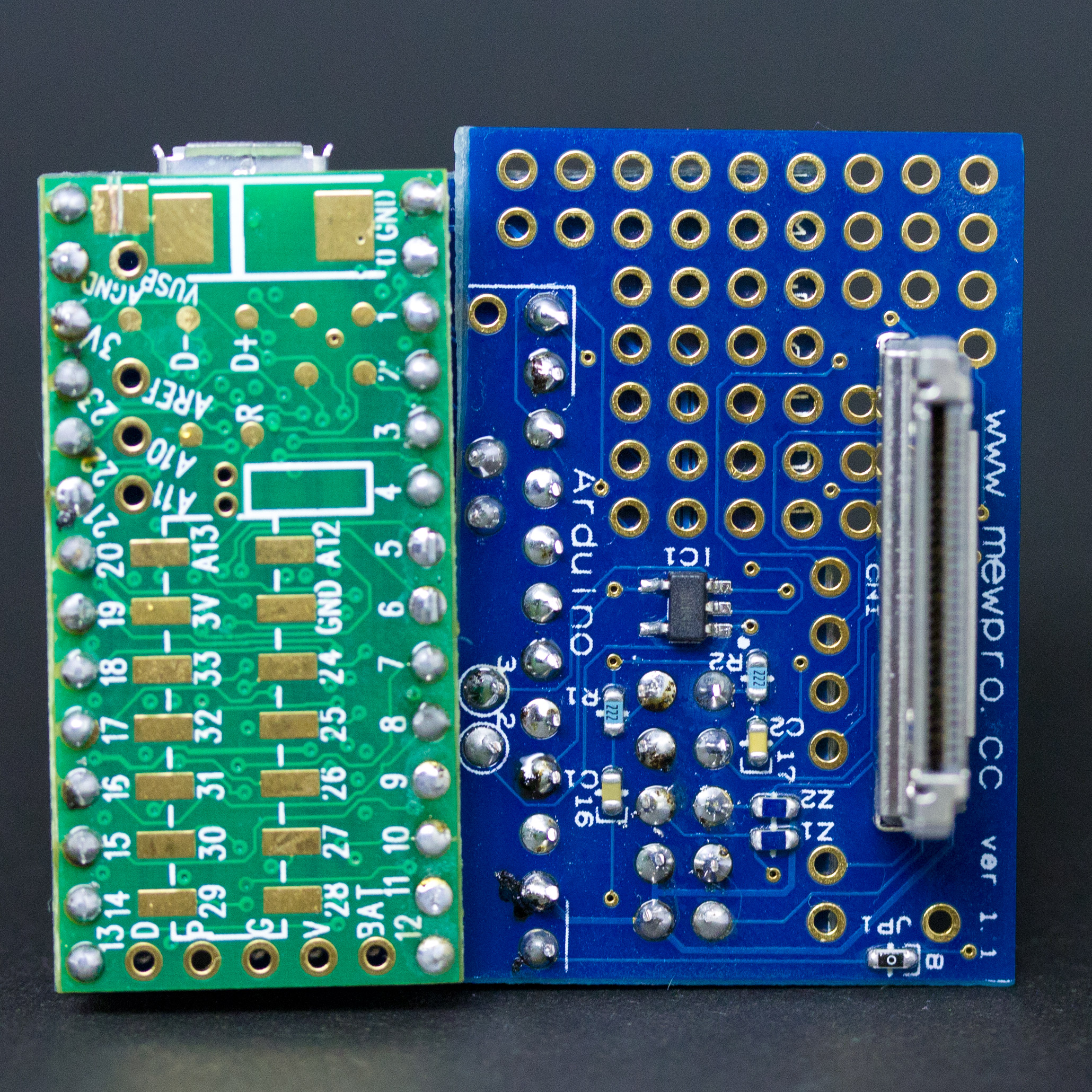
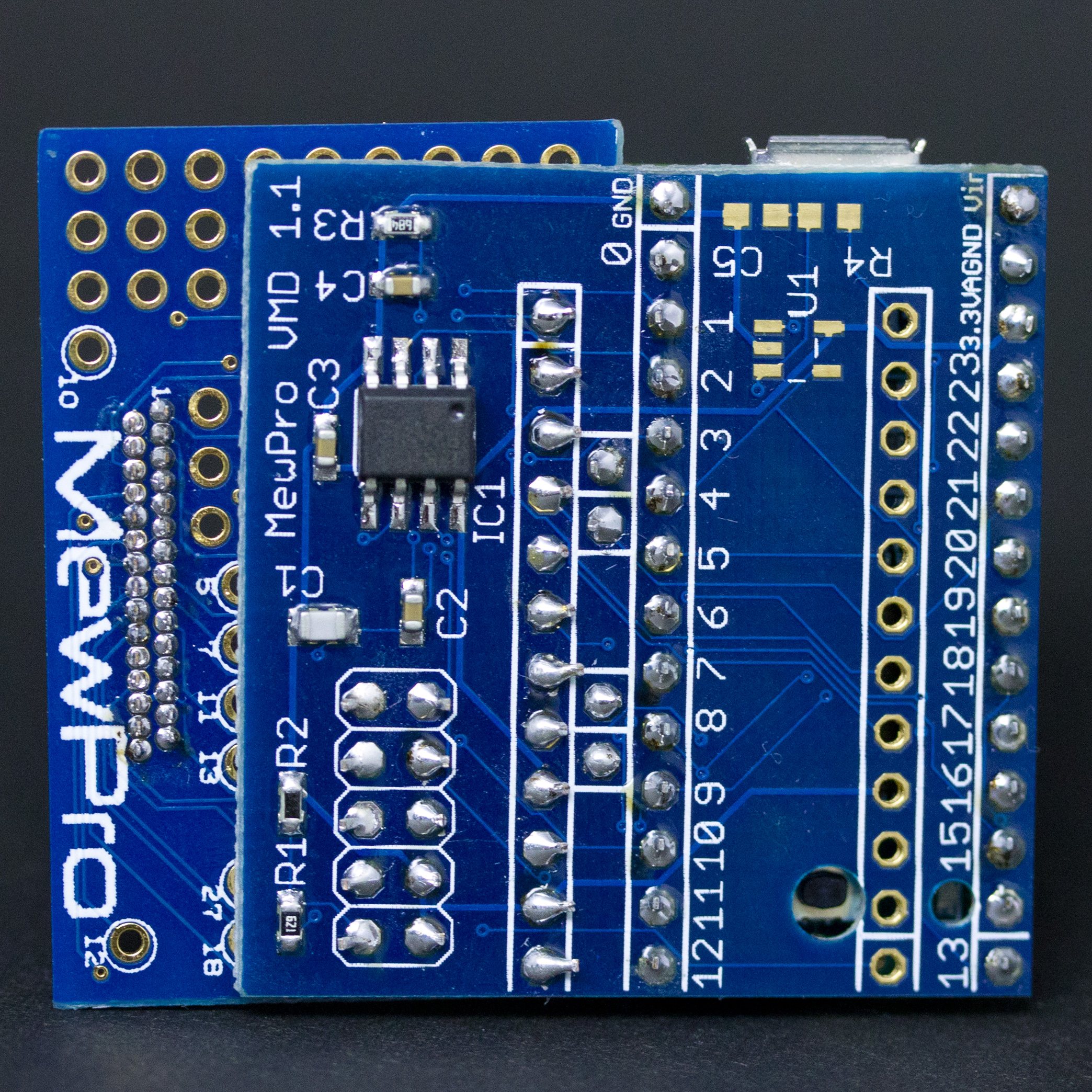
MewPro
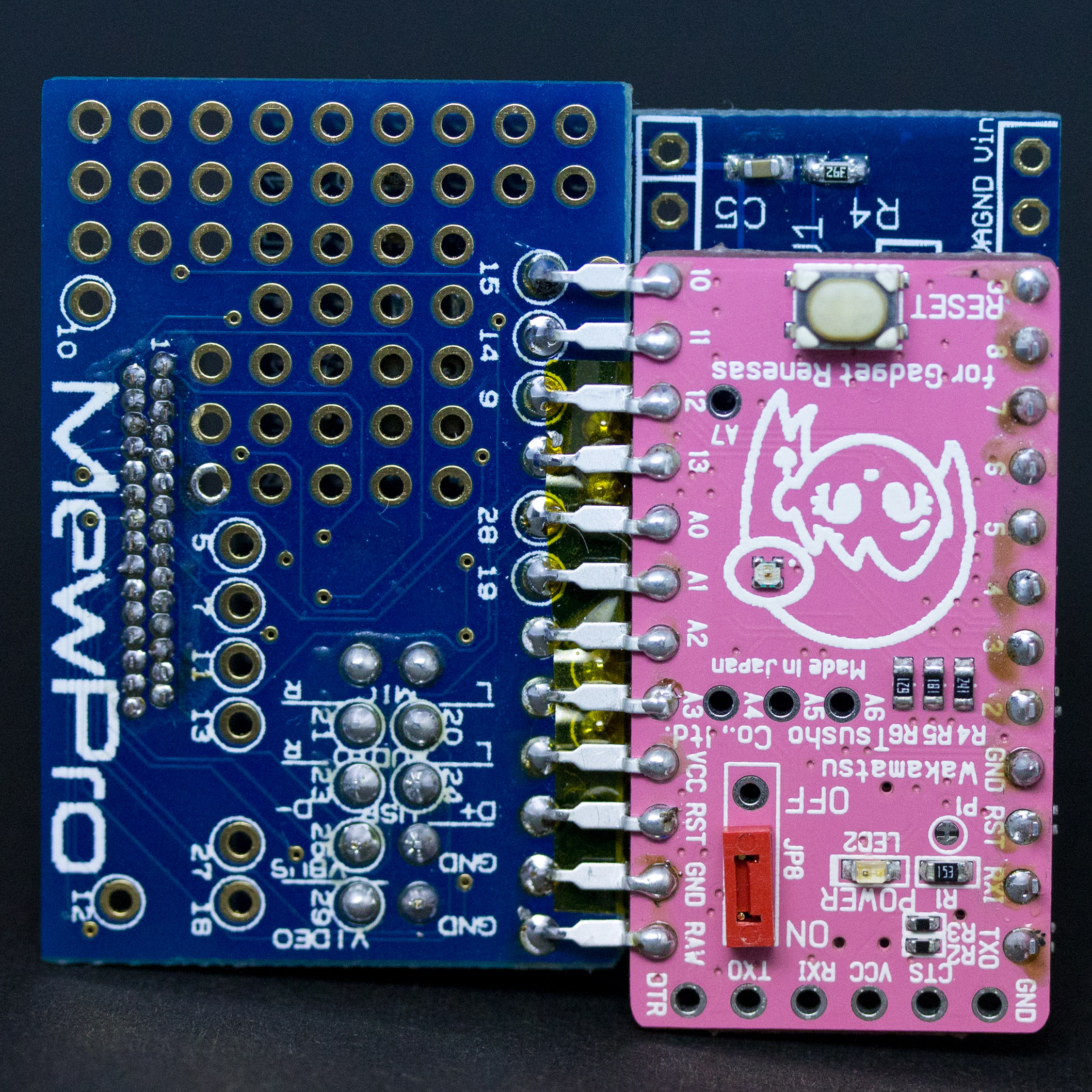
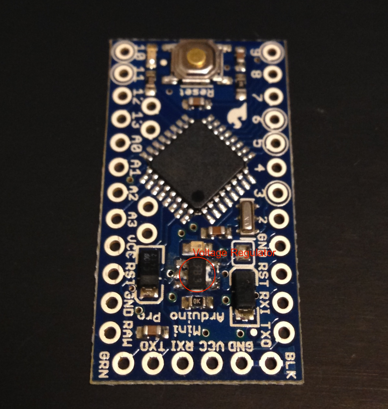
SMD parts, Herobus connector and Arduino Pro Mini 3.3V 8MHz are soldered. If you want to use a higher performance microcontroller then Teensy 3.1 and GR-KURUMI are supported by the MewPro application.
Arduino Pro Mini Temporary FTDI Header
If you buy a MewPro from our shop the header is included in the package.
Sparkfun FTDI Basic Breakout – 3.3V and USB cable
Use 3.3V version of the breakout board. Any compatible board should work.


Remark: If you use Teensy 3.1 in the place of Arduino Pro Mini then you don’t need Temporary FTDI Header and/or Sparkfun FTDI board; and please consider to buy our Arduino Pro Mini / Teensy 3.1 Conversion Board.

Teensy Warning: If you use Teensy 3.1 with MewPro, please cut the PCB pattern between VUSB and VIN (On the a-lot-of-pad-side of Teensy board there is the special slit between pads to do so). Because MewPro uses RAW input from GoPro battery (about 3.8V). So if you connect VUSB (5V) to MewPro’s RAW then GoPro’s battery pin will become 5V. This will destroy your GoPro.

Softwares:

Arduino IDE 1.5.7 beta or newer
Older versions of Arduino IDE have bugs in Wire library that cause MewPro unusable.
MewPro Application
This is an open source software (MIT license). You can modify and distribute it as you like.


Remark: If you use Teensy 3.1 or GR-KURUMI, you must be a wizard or witch so maybe you know what is required a kind of softwares instead of above mentioned Arduino IDE.


Connection

Install Arduino IDE on your PC and launch it. In Arduino IDE [File]→[Open...]→ then open MewPro.ino.

Remark: MewPro.ino contains the following files as tabs; a_Queue.ino, b_TimeAlarms.ino, c_I2C.ino, d_BacpacCommands.ino, e_Shutter.ino, f_Switch.ino,g_IRremote.ino, h_LightSensor.ino, i_PIRsensor.ino, and j_VideoMotionDetect.ino. If you like to see what will be happen inside of your Arduino Pro Mini you could read any of them.

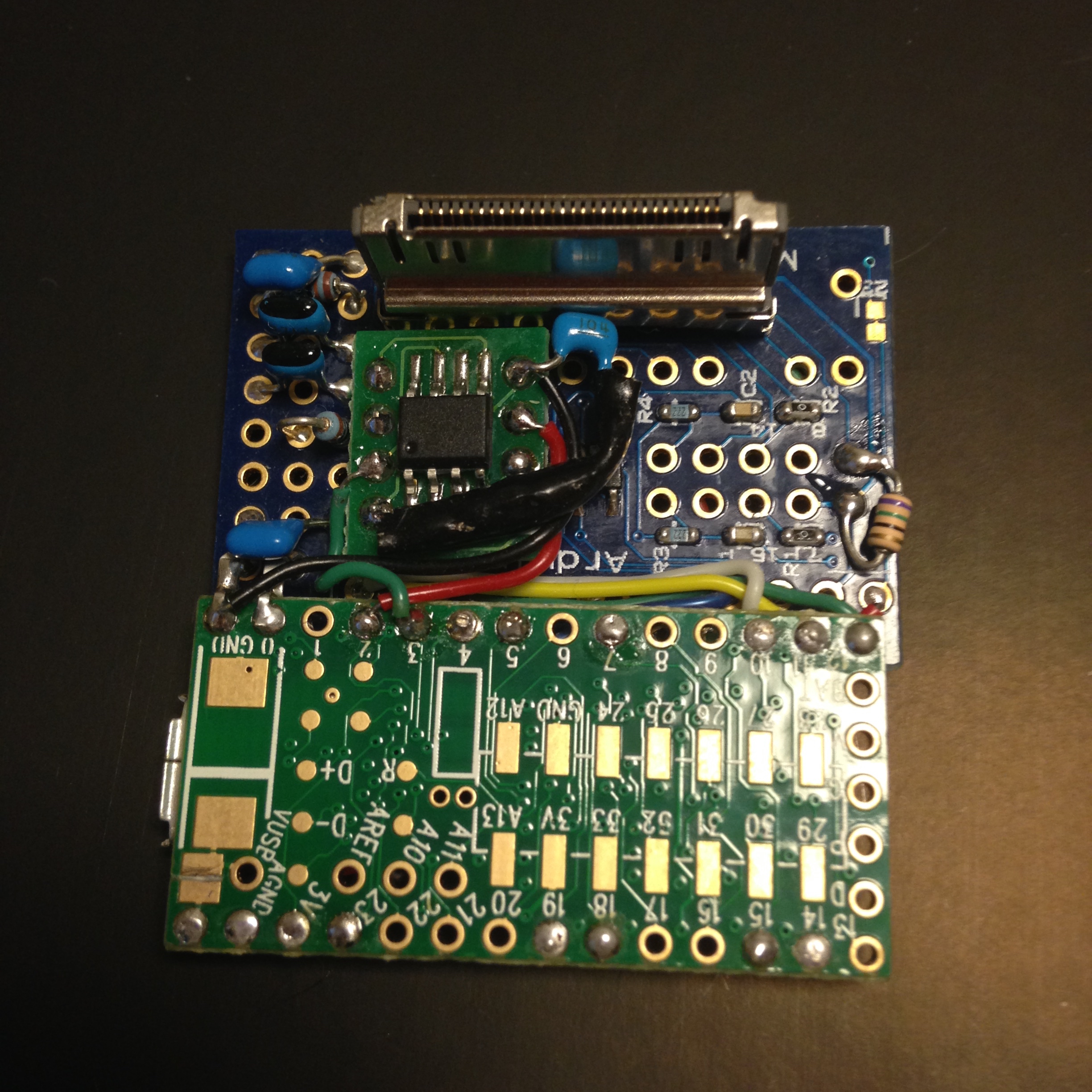
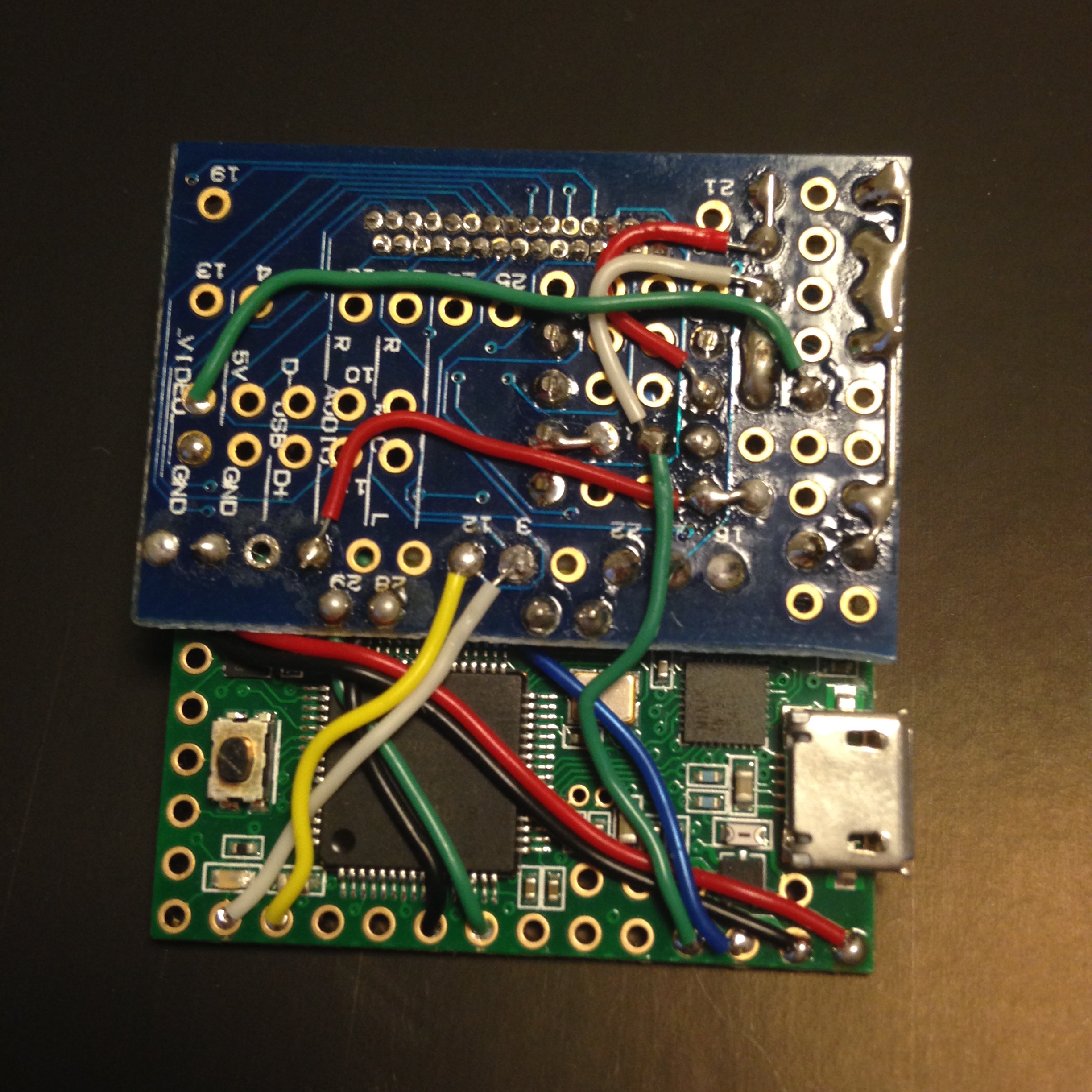
Connect MewPro to your PC w/ FTDI board and the temporary header.
IMG_5942
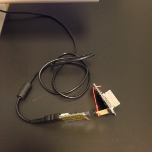
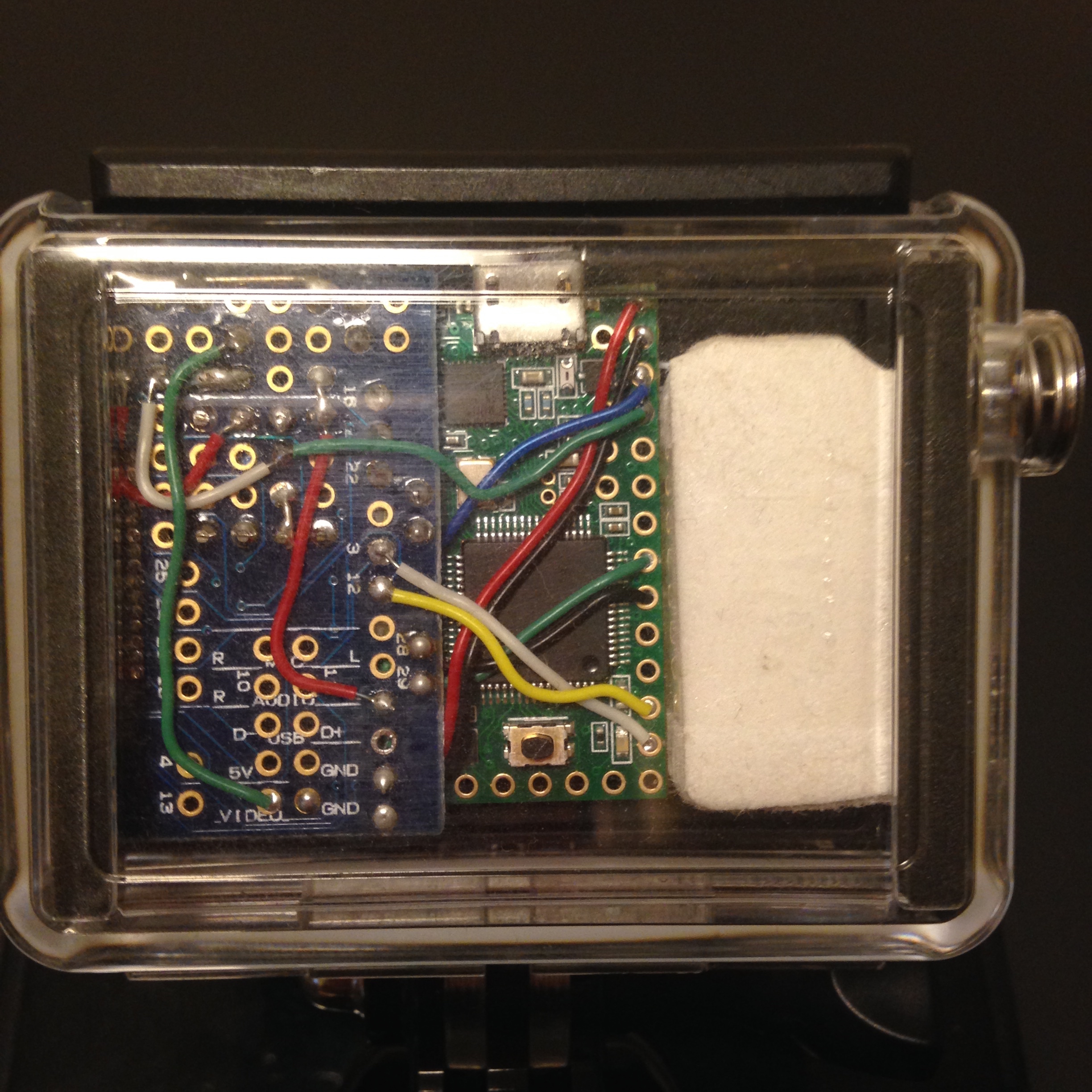
Then connect them to GoPro Hero 3+ Black.
IMG_5943

In Arduino IDE application, select [Tools]→[Board]→[Arduino Pro or Pro Mini], [Tools]→[Processor]→[ATmega328 (3.3V, 8MHz)], and [Tools]→[Port]→[(the port where you connected the FTDI cable)]. Then “Verify” the MewPro sketch and “Upload” it to Arduino Pro Mini board.

Remark: If you are using Teensy 3.1 c_I2C.ino will fail to compile. Just change the first four lines to
#if defined(__MK20DX256__) // Teensy 3.1
#include <i2c_t3.h> // *** please comment out this line if __MK20DX256__ is not defined ***
#else // Arduino Pro Mini
//#include <Wire.h> // *** please comment out this line if __MK20DX256__ is defined ***


Control GoPro

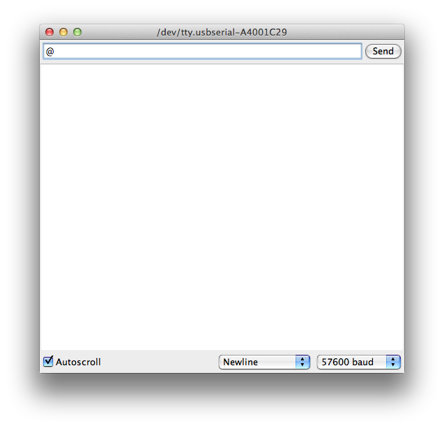
Open “Serial Monitor” in Arduino IDE window (click the the top right “magnifier” icon). Set [57600 baud] using the bottom right pulldown, [Newline] the middle pulldown, [Autoscroll] the left box checked.

11.57
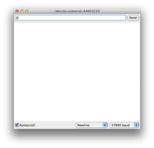
Type ‘@‘ (one letter representing at sign) in the input area of Serial Monitor, and hit return key.

12.00
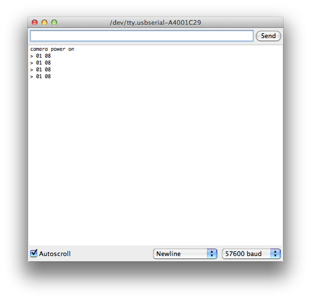
The message “camera power on” is shown and your GoPro Hero 3+ Black turned its power on.

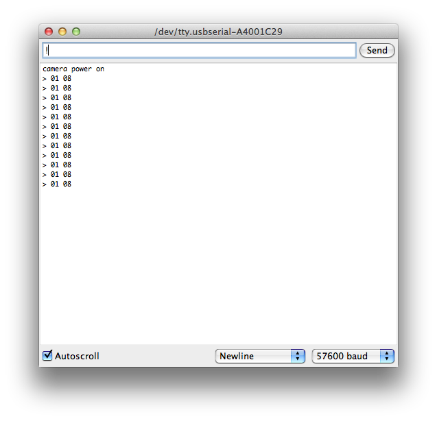
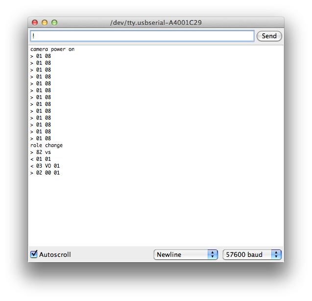
The messages on “Serial Monitor” shows communication details between Arduino and GoPro. If this is the first time to connect your MewPro to GoPro then repeated erroneous “>01 08” is shown again and again. This is because the I²C EEPROM on the MewPro board is not properly initialized yet. So let’s type another one letter command ‘!’ (exclamation mark) in the input area of Serial Monitor, and hit return key.

12.001

Then other messages come from GoPro.
12.002
“role change” means that the role as a BacPac™ has been changed. This time the role is “master” (to understand the roles and modes of Dual Hero BacPac™ please refer our previous post).

In “master” role, we can’t push the shutter botton. But we can get composite video signal out of Herobus connector by using “VO1” command, which “master” MewPro automatically send to GoPro as shown in messages of above screenshot.

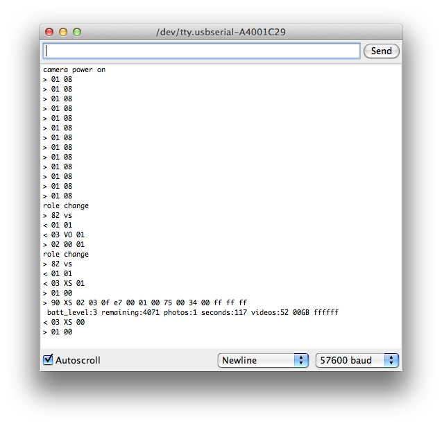
Next change the role to “slave”. To do this, type the one letter command ‘!’ again. The command ‘!’ toggles the role between “master” and “slave”.
12.003
12.010

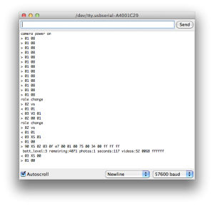
You can see in the above screenshot various information is obtained from GoPro camera.

Now I²C EEPROM on your MewPro board is properly set to “slave” role. In the role we can push the shutter button of GoPro as usual. So we recommend using MewPro in this role.

Now we almost do every thing on GoPro from Arduino. Details of I²C commands are listed in our earlier post.

Try typing “SY1”. Then “SY0”. (Start recording! Stop recording!!)

If you finished type “PW0”. (This should power off your GoPro.)

Enjoy!


Final Note: “SY1” command fails if the mode is different to the mode when GoPro is power on. That is if you change camera’s mode manually by using mode/power button of the camera body or “CM” (SET_CAMERA_MODE) command, then “SY” command will fail. This is due to GoPro firmware so please don’t blame MewPro. In order to workaround this restriction, use “DM” (SET_CAMERA_DEFAULT_MODE) command and set your camera to desired mode and “PW0” (power off). After this, try ‘@‘ (power on) and “SY1“.