Posted on Leave a comment

Mounting GoPro’s microSD thru Side USB

By installing a slide switch or an alternate push button to the reset line of our genlock system, GoPro’s microSDs get easily accessible from PC through the USB on the side.

The customer in Germany recently told us that they succeeded in mounting GoPro’s microSDs without detaching MewPros nor soldering additional wires. They’ve got two key ideas: 1. If the reset line is kept LOW then MewPros don’t logically exist on Herobus; 2. If Dual Hero bacpac (or MewPro) is attached to Herobus then the side USB cannot be used to mount GoPro’s microSD from PC.

We misunderstood that the I2C command “UM0” enabled access to internal microSD from the side USB. The truth is the command only disables access from the back USB that have been enabled by “UM2”, and resumes the 3D mode.

The following is a demo to mount all the microSDs in a sample rig.

Example Session

The rig is in a single-dongle configuration with one master camera and, for simplicity sake, only one slave camera. All cameras and the Dual Hero bacpac are powered/charged by a self-powered USB 2.0 hub. An alternate push button switch is installed on the reset line (the red part in the photos below. When the button is pushed/latched its red rod is seen shorter).

Step 0: Let’s start this session with normal charging state: Master camera is OFF; Slave camera(s) OFF; USB hub’s power is ON; Reset line HIGH, i.e., reset is OFF.

Master OFF. Slave OFF. USB hub ON. Reset OFF.

Step 1: Push the master camera’s power button. Then the system enters in 3D shooting state.

Master ON (3D). Slave ON (3D). USB hub ON. RESET OFF.
Master ON (3D). Slave ON (3D). USB hub ON. Reset OFF.

Step 2: Push and hold the reset switch to keep the reset line LOW. And temporally detach power from the USB hub. Then the master camera becomes automatically OFF because the peer Dongle has lost its power.

Master OFF. Slave ON (not 3D). USB hub OFF. Reset ON.

Step 3: Plug a USB cable to PC and hub. And power on the USB hub.
Then the slave camera(s) become(s) hard disk mode and they are accessible from PC simultaneously.

Master OFF. Slave ON (disk). USB hub ON and connected to PC. Reset ON.

Step 4: After downloading video/image data from slave GoPros unmount these disks on PC. And push release the reset line.

Master OFF. Slave ON (3D). USB hub ON and connected to PC. Reset OFF.

Step 5: We have downloaded data from all the cameras but the master. Now push the master camera’s power button again. Then we will be able to do the job.

Master ON (disk). Slave ON (3D). USB hub ON and connected to PC. Reset OFF.

Posted on Leave a comment

How To Use MewPro 2 and Application

We will show you basics to use MewPro 2 for controlling GoPro Hero 3+ Black camera.

The post involves no external sensors.

UPDATE 25 Feb. 2017: Hero 4s are now supported: Please refer this post.

mew2-11


Prerequisites

In order to use MewPro 2 as a GoPro controller you need the following hardwares:

GoPro Hero 3+ Black
No previous editions work with MewPro 2.
MewPro 2
MewPro 2 is ready to use without soldering.
Arduino Pro Mini Temporary FTDI Header
If you buy a MewPro 2 from our shop the header is included in the package.
Sparkfun FTDI Basic Breakout – 3.3V and USB cable
Use 3.3V version of the breakout board. Any compatible board should work.

Softwares:

MewPro 2 is shipped with optiboot as well as MewPro software (for genlock) installed. But if you like to modify/update the software you will need to prepare the following IDE, core and library. To install each software please refer their documentations.

Arduino IDE 1.6.5 or newer
Older versions of Arduino IDE might work but we don’t confirm that.
ATTiny Core
1634, x313, x4, x41, x5, x61, x7, x8 and 828 for Arduino 1.6.x
WireS library
Slave only hardware Wire library for ATtiny1634 microcontroller.

Lastly grab the MewPro application:

MewPro Application
This is an open source software (MIT license). You can modify and distribute it as you like.

Connection

On your PC launch Arduino IDE that was installed as described in the above. In Arduino IDE [File]→[Open...]→ then open MewPro.ino.

Remark: MewPro.ino contains the following files as tabs; a_Queue.ino, b_TimeAlarms.ino, c_I2C.ino, d_BacpacCommands.ino, e_Shutter.ino, f_Switch.ino,g_IRremote.ino, h_LightSensor.ino, i_PIRsensor.ino, j_VideoMotionDetect.ino, and k_Genlock.ino. If you like to see what will be happen inside of your ATtiny1634 you could read any of them.
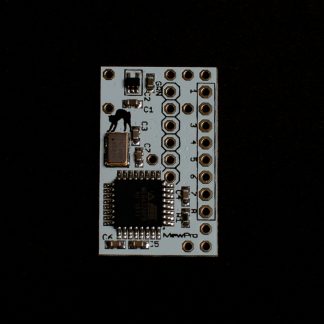
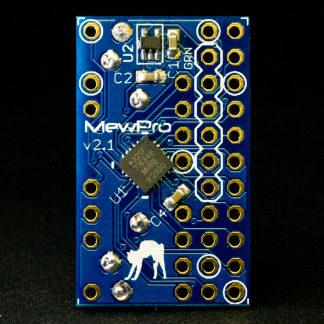
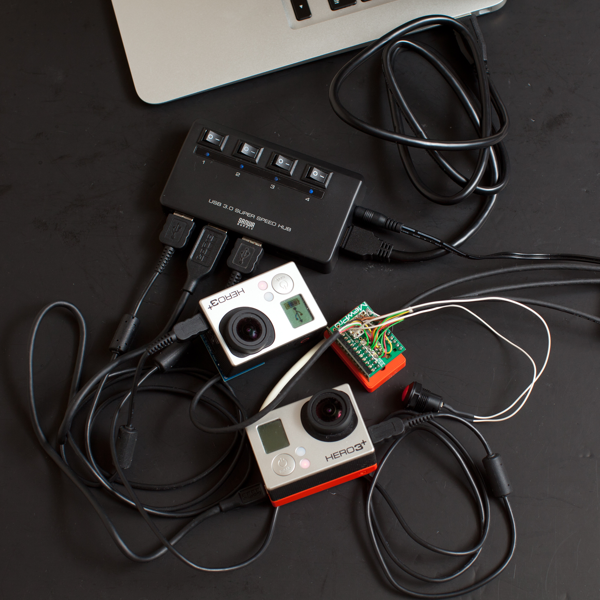
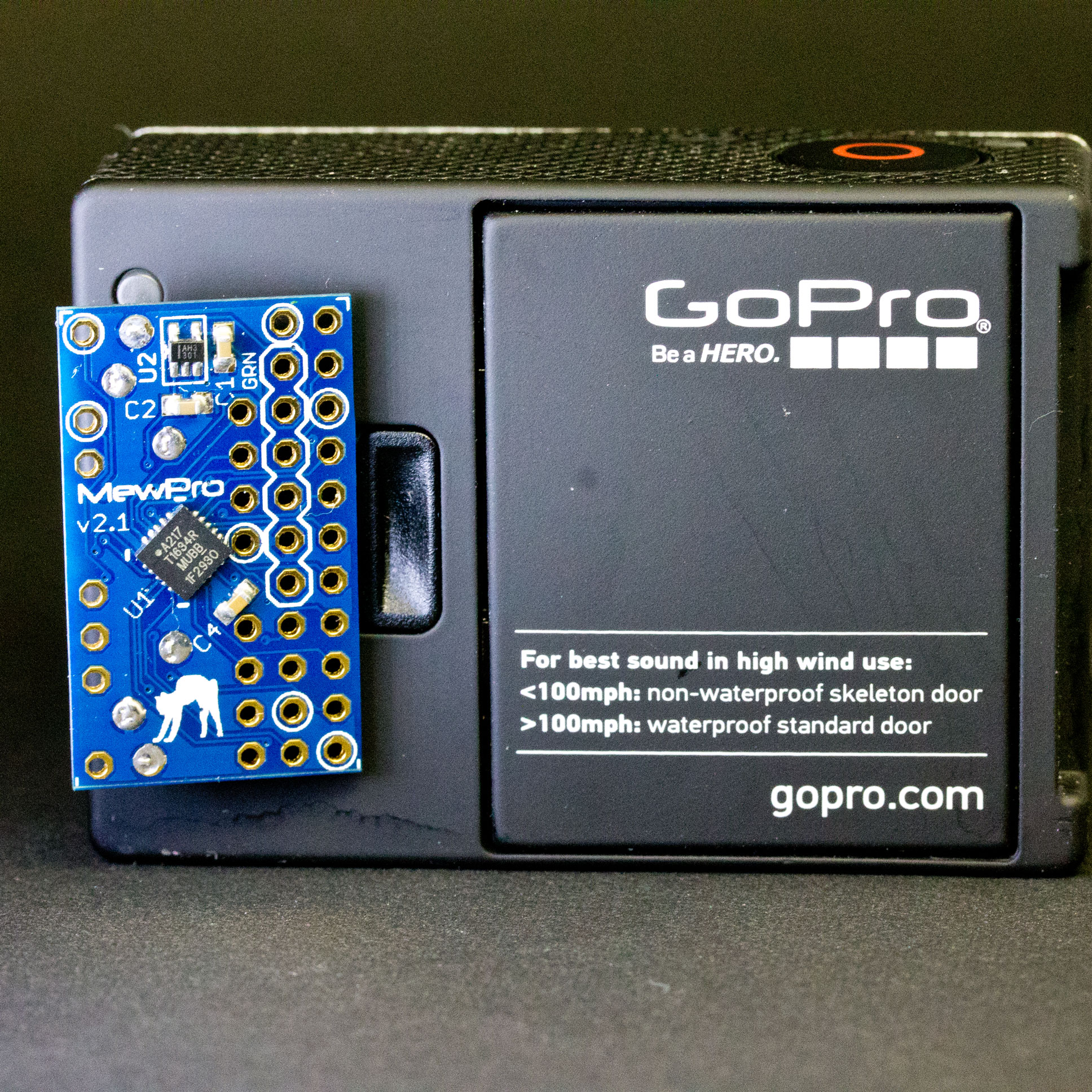
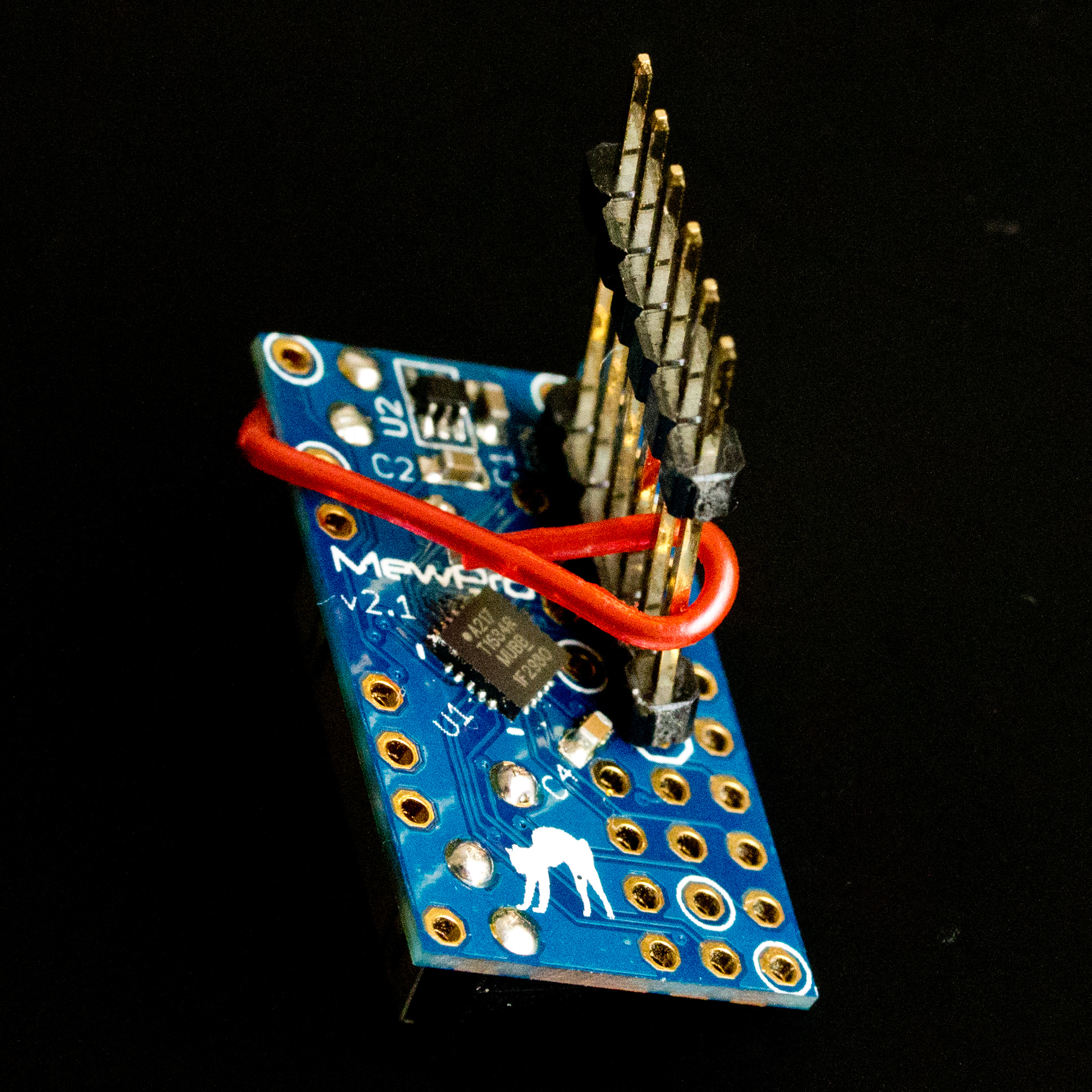
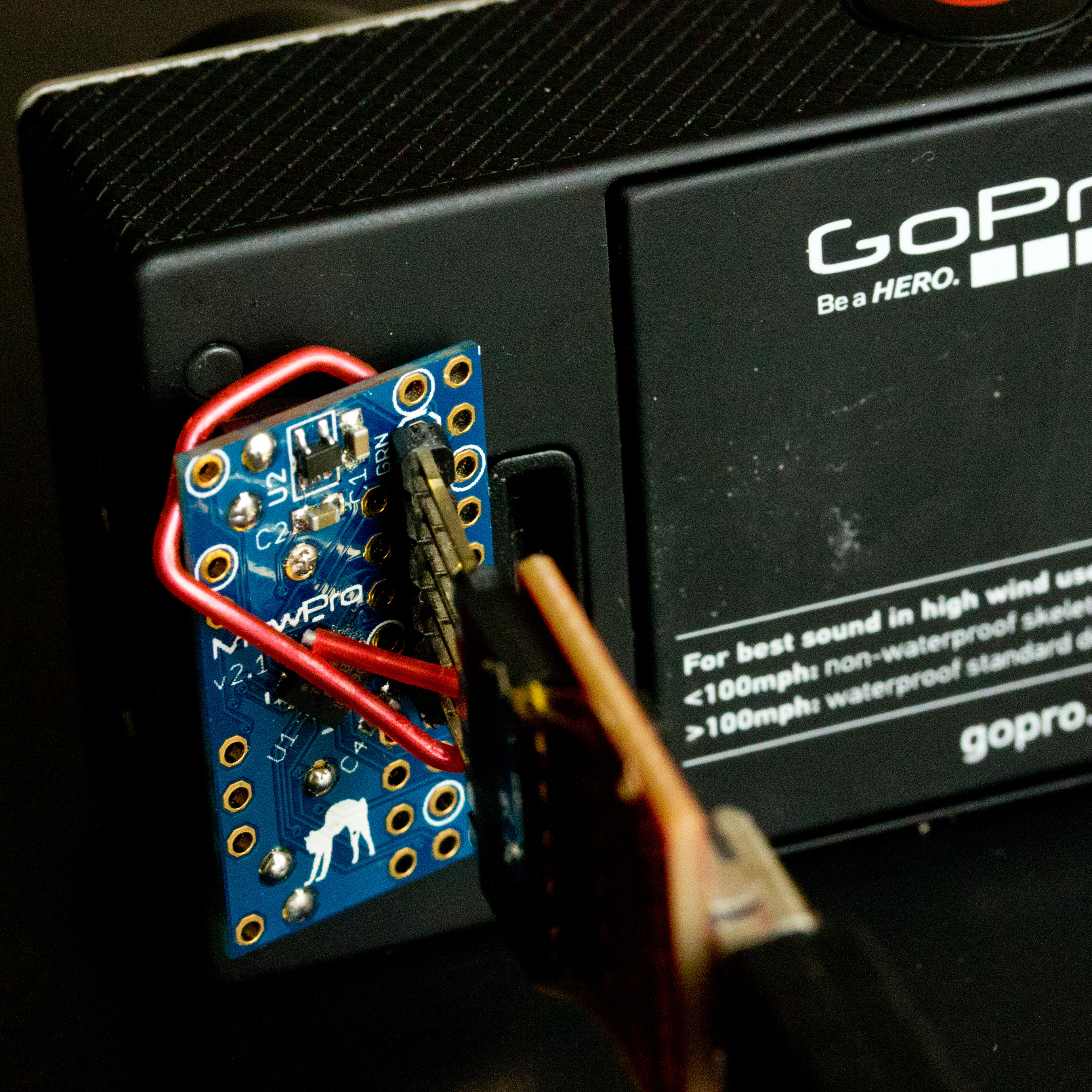
Connect MewPro 2
connection2

to your PC w/ FTDI board and the temporary header.
conne2

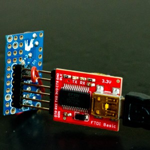
Connecting FTDI please refer the pinout image below:
MewPro2

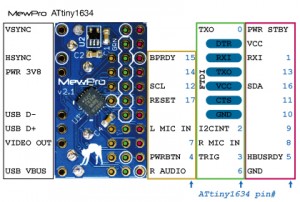
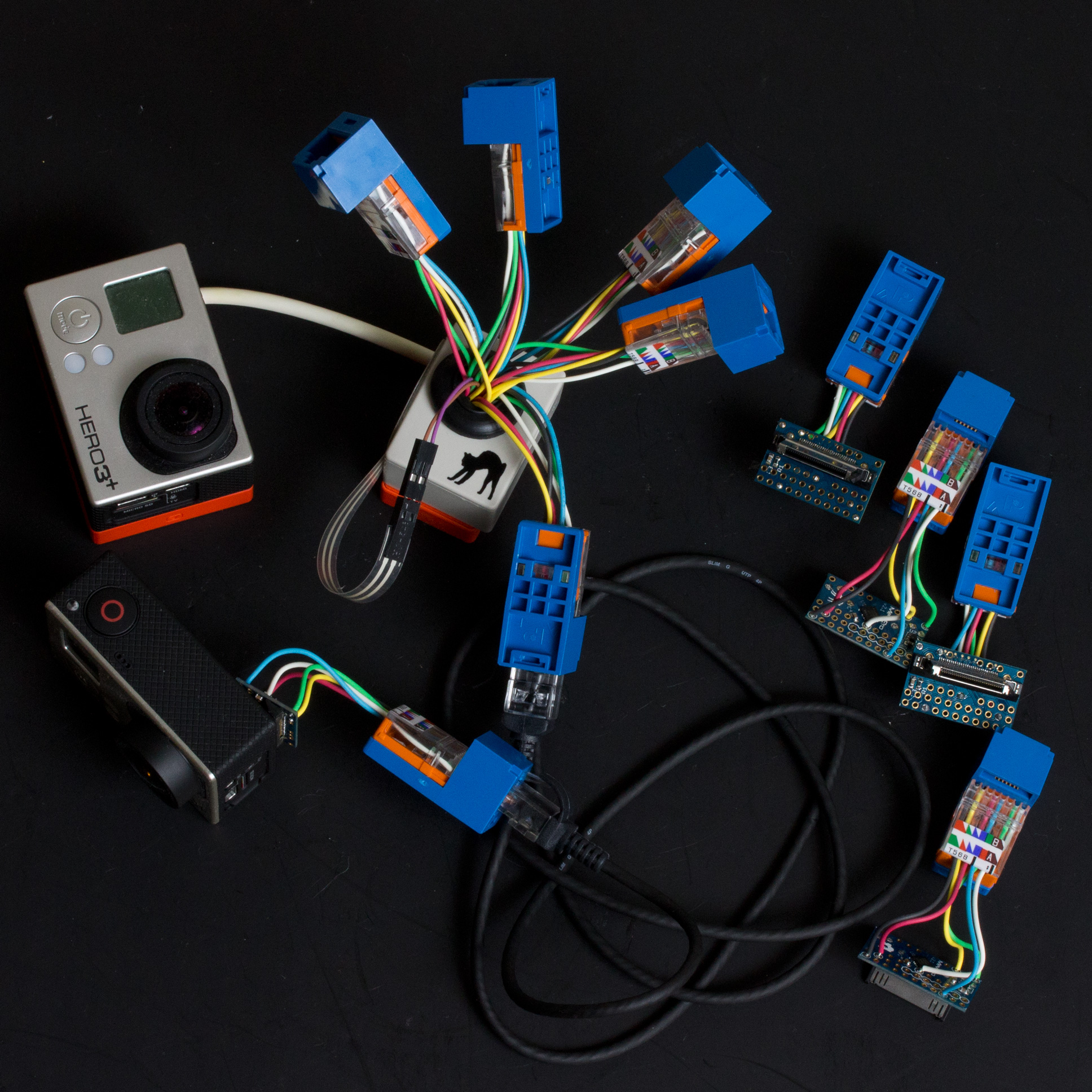
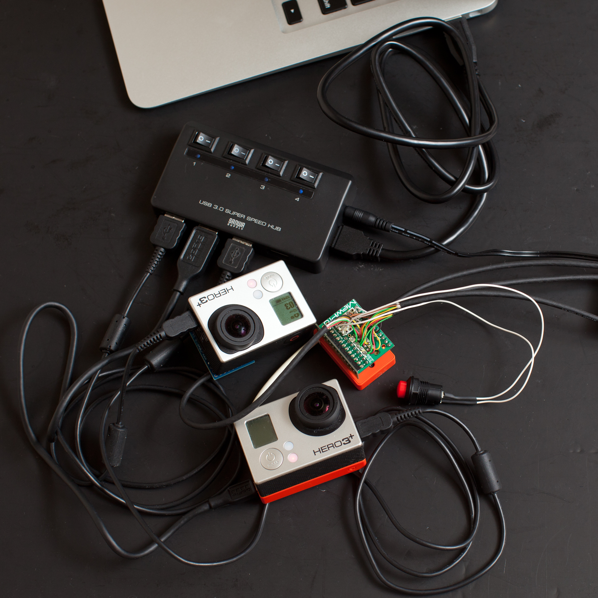
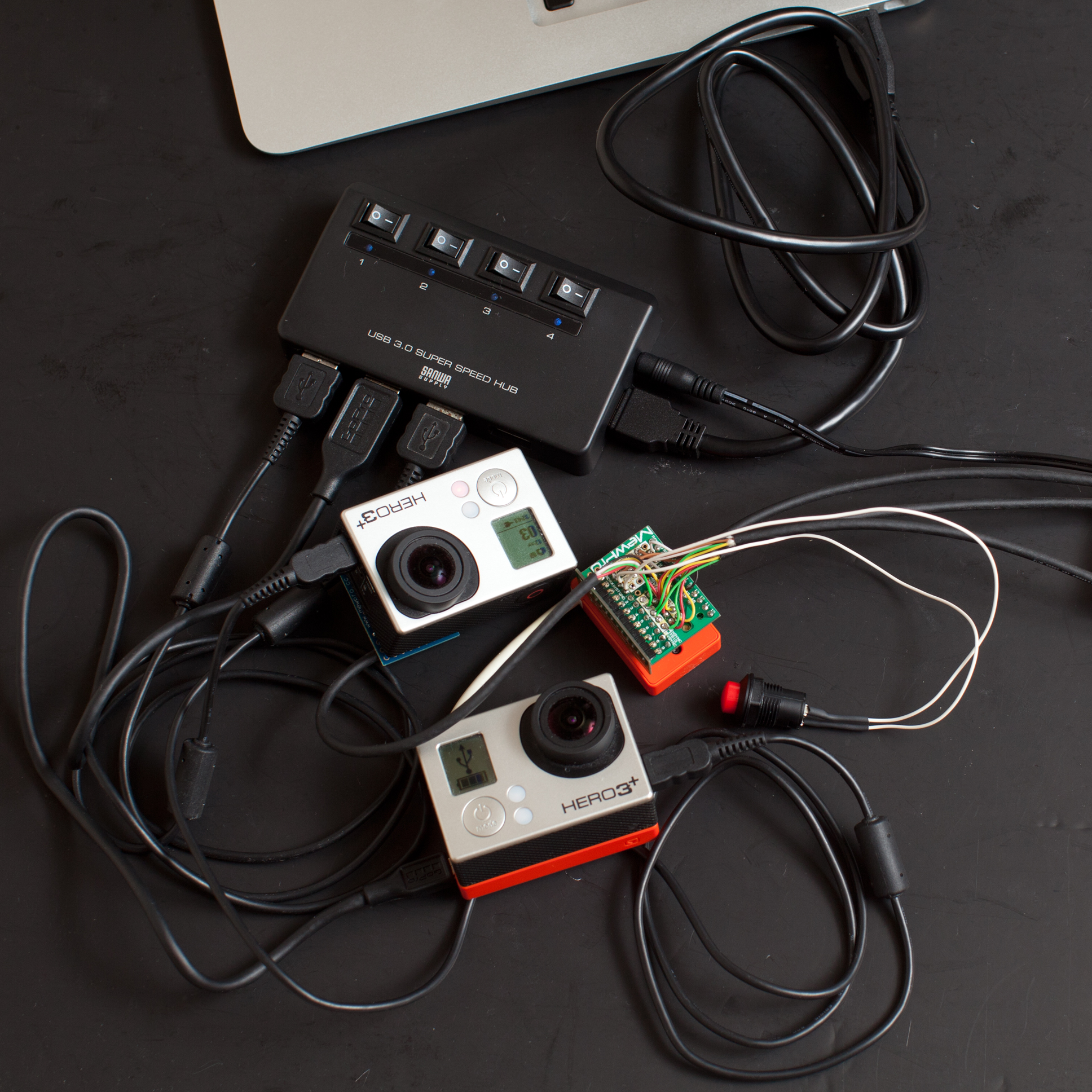
Then connect them to GoPro Hero 3+ Black.
conne1

In Arduino IDE application, select [Tools]→[Board]→[ATTiny1634 (optiboot)] and [Tools]→[Port]→[(the port where you connected the FTDI cable)]. (B.O.D. and Clock settings are “don’t care” as these values are only effective when you burn a bootloader to the microcontroller by using an ISP programmer.)

The MewPro source code is originally targeted to MewPro 1, Arduino Pro Mini, so please change the following lines in MewPro.ino from

#include <Wire.h> // *** please comment out this line if __MK20DX256__ or __MK20DX128__ or __MKL26Z64__ or __AVR_ATtiny1634__ is defined ***
#if BUFFER_LENGTH < 64
#error Please modify Arduino Wire library source code to increase the I2C buffer size
#endif
//
// Teensy 3.0 or 3.1 or LC
//#include <i2c_t3.h> // *** please comment out this line if __MK20DX256__ and __MK20DX128__ and __MKL26Z64__ are not defined ***
//
// ATtiny1634 core https://github.com/SpenceKonde/arduino-tiny-841
// WireS library is downloadable from https://github.com/orangkucing/WireS
//#include <WireS.h> // *** please comment out this line if __AVR_ATtiny1634__ is not defined ***

to

//#include <Wire.h> // *** please comment out this line if __MK20DX256__ or __MK20DX128__ or __MKL26Z64__ or __AVR_ATtiny1634__ is defined ***
//#if BUFFER_LENGTH < 64
//#error Please modify Arduino Wire library source code to increase the I2C buffer size
//#endif
//
// Teensy 3.0 or 3.1 or LC
//#include <i2c_t3.h> // *** please comment out this line if __MK20DX256__ and __MK20DX128__ and __MKL26Z64__ are not defined ***
//
// ATtiny1634 core https://github.com/SpenceKonde/arduino-tiny-841
// WireS library is downloadable from https://github.com/orangkucing/WireS
#include <WireS.h> // *** please comment out this line if __AVR_ATtiny1634__ is not defined ***

that is, to use the WireS library instead of the standard Wire library.

The code should now be compiled successfully.
Verify” the MewPro sketch and “Upload” it to MewPro 2 board.

Remark: If you are using MewPro 2 board for genlocking, please modify MewPro.ino as

boolean debug = false;
#define USE_GENLOCK

and for MewPro #0 in double dongle configuration

#define UART_RECEIVER_DISABLE

Control GoPro

Controlling details through Arduino console is the same as MewPro 1.


Resources

Posted on Leave a comment

MewPro in Jǐnán China

MewPros to synchronize a 40-camera motion capture system for studying bats during flight, Hunter McClelland (hgm at vt dot edu) a researcher working with Shāndōng University, Jǐnán, China, and Virginia Tech University told us today.

The following photos are courtesy of Hunter McClelland, Dr. Rolf Mueller (project leader), Matt Bender (senior code developer) and the team of researchers:

Many GoPros with MewPro
Dual Hero and Genlock Dongles
Flight tunnel
Flight tunnel
Soldering wires to MewPros and Dongles...
Soldering SMD parts and wires to MewPros and Dongles…

We are very glad to hear about this kind of user reports. 🙂

Bug Reports

The above team of researchers also found some issues in MewPro+Dongle system including:

A) start-frame error, i.e. cameras begin frame 1 of their videos at different starting times.
This turned out to be a bug in Genlock Dongle code and should be fixed now.
B) inner-frame delay, i.e. cameras are not taking pictures at exactly the same time.
To genlock every scan line must nearly attain image sensor’s performance limit. So we don’t think this is a bug in our system and/or signaling.

These kind of bug reports are also welcome as MewPro is an open source project.