In this post we present some suggestion, “overclocking” on 3.3V and 16MHz Arduinos.
Processors from Atmel are usable on both 5V and 3.3V logics. For example, ATmega328P on Arduino Pro Mini or ATmega32U4 on Arduino Leonardo (Arduino Pro Micro) can work on both voltages without problems. But only one consideration is remained: 16MHz clock is not OFFICIALLY supported by Atmel if the processor is on 3.3V. So if you use these processors at 3.3V AND 16MHz you must understand/agree you are in danger(!) of overclocked them. (However, in many cases it should be safe and no problem.)
In this post we’ll do two overclocking experiments:
- Arduino Pro Mini 328 5V 16MHz → 3.3V 16MHz
- Arduino Leonardo (5V 16MHz) → (3.3V 16MHz)
1. Making Arduino Pro Mini 328 3.3V 16MHz
If you want Arduino Pro Mini 328 3.3V “16MHz” then there might be another way: Buy a genuine Arduino Pro Mini 328 3.3V “8MHz” and change the crystal (CERALOC® = ceramic resonator) on it. The problem is NO COMPATIBLE CERALOC® exists for the original one (original part no. is Murata CSTCE8M00G55A-R0). To be more precise, Murata makes a similar CERALOC® of 16MHz (part no. Murata CSTCE16M0V53-R0) but their footprints differ and 16MHz version can’t fit to the 8MHz place. So this method to change the crystal is not so easy to go through.
Thus we try the other way: Buy a genuine Arduino Pro Mini 328 “5V” 16MHz and change the voltage regulator on it. Photo: The location of regulator is marked red. The original voltage regulator is Micrel MIC5205-3.3YM5. It is the LoHS version of Micrel MIC5205-3.3BM5 and the footprint is SOT-23-5.
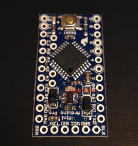
(Sorry. I forgot to take a picture of original Arduino Pro Mini 328 5V 16MHz. The voltage regulator in this photo has already replaced by a 3.3V regulator.)
I used some low temperature solder (Removal Alloy by CHIPQUIK®) and two soldering irons to remove the SMD regulator. Detailed instruction of removing SMD parts is there in CHIPQUIK® site.
The replacement part should be any 3.3V voltage regulator that holds certain conditions. If you happen to get a Micrel MIC5205-3.3YM5 (LoHS) or Micrel MIC5205-3.3BM5 (non-LoHS) then you are very lucky to use the best one. However, the required conditions are, I think, only “3.3V fixed voltage”, “low dropout”, “150mA”, and “SOT-23-5” so there are many choices in buying a compatible regulator.
I used a Toshiba TAR5SB33 for the replace, because it is already there just in my parts-box. Soldering a SOT-23-5 part is not so difficult and is fun!
After soldering, connect the Arduino to your PC and check how it works (Don’t forget to use 3.3V version of FTDI board!!). In Arduino IDE, [Tools]→[Board] should be “Arduino Pro or Pro Mini” and [Tools]→[Processor] should be “ATmega328 (5V, 16MHz)” (Note: Arduino IDE doesn’t care about the voltage).
2. Making Arduino Leonardo (3.3V 16MHz)
There is a great article by Tyler Cooper on replacing Arduino Uno’s regulator to a 3.3V version. Arduino Uno and Leonardo are nearly identical around the power circuit (you can compare their schematics: Uno, Leonardo) so we could do the same on Leonardo, too.
However, the method Cooper used for Uno is not good for Leonardo who can speak some of USB protocols. Because after his surgery of removing the fuse XUSB signal doesn’t reach Uno’s (or Leonardo’s) processor pin but nowhere. USB 2.0 protocol requires XUSB (= VUSB) line to be alive (for checking impedances to D+/D-) at least speed negotiation phase thus the line shouldn’t be remained at infinite impedance or open after the surgery.
So I didn’t remove the fuse but did remove the MOSFET (T1 FDN340P in the schematic) marked red in the following photo.
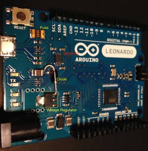
(Sorry, again. I also forgot to take a photo before removing/replacing something. In this photo the MOSFET has already removed, the voltage regulator replaced, and the additional diode attached.)
The rest of the surgery is the same as Cooper’s method: Replace the voltage regulator to a 3.3V version and connect VUSB to voltage regulator’s input pin through a diode. I used Advanced Analog Circuits AZ1086H-3.3 (SOT-223 package) for voltage regulator and 1N4007 for diode, however, any similar ones will do.
After removal and soldering things, connect the Arduino to your PC and check how it works. In Arduino IDE, no changes in settings are required (i.e., [Board] is also “Arduino Leonardo” and that’s all).
Enjoy!

