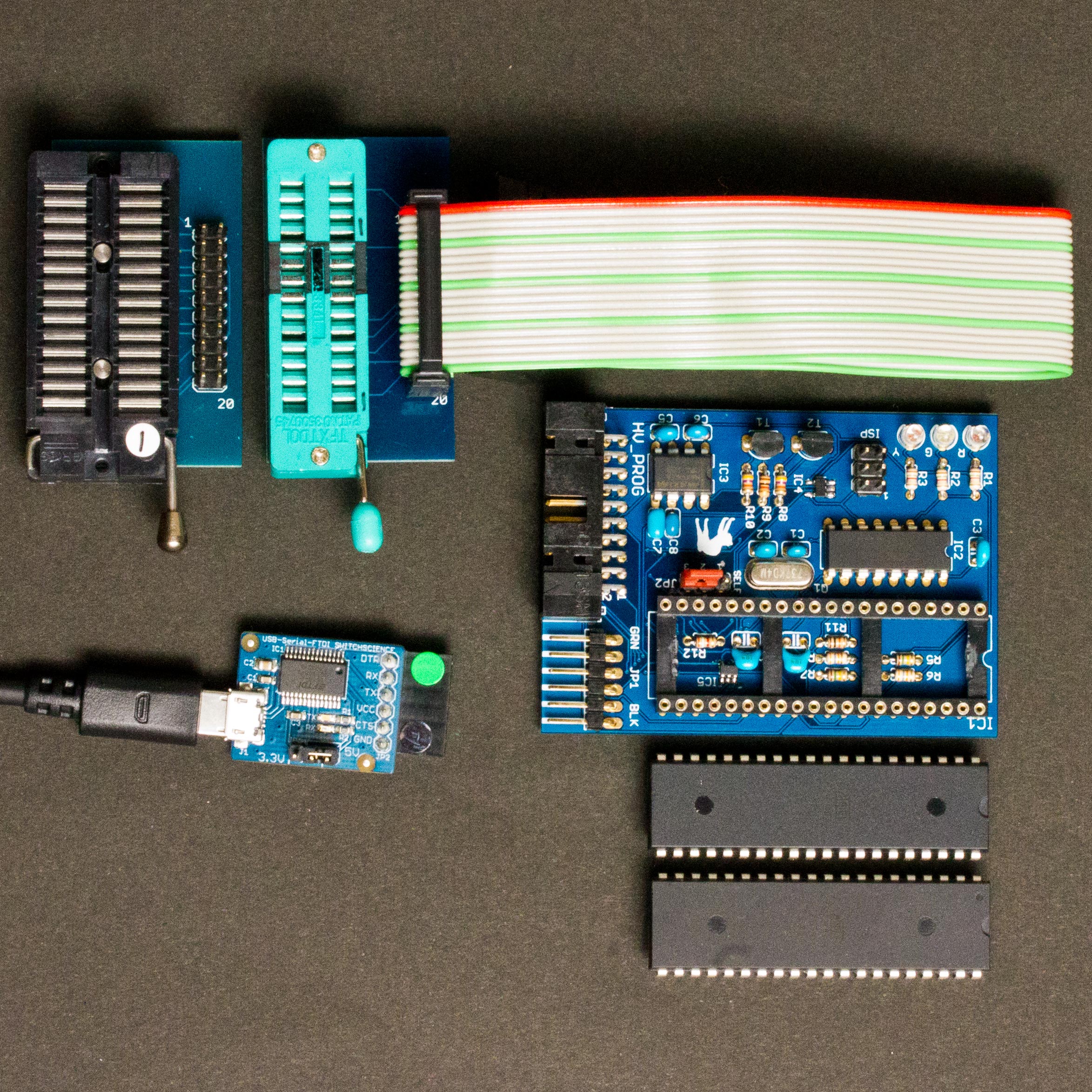
HVprog2 is an Atmel STK500 clone for programming in HVSP/PP, ISP, TPI, and PDI. This post explains how to use HVprog2.
Note: This and the previous posts are nothing to do with GoPro nor genlock. These discuss some programmers for AVR microcontrollers.
In the previous post we showed a hardware/software mod of original Atmel STK500. Inspired both by Atmel STK500 and its mod we designed a clone programmer called HVprog2.
There already exists another hardware clone of Atmel STK500 whose name is HVprog, and it claims to be able to program in HVSP/PP and ISP. HVprog2 is an improved version of HVprog, thus it has a similar name, and it can actually program AVR chips not only in HVSP/PP and ISP but also in TPI and PDI.
Comparison With STK500 original/mod, HVprog and HVProg2
The below is a comparison chart of AVR programmers:
|
STK500 |
STK500 mod |
HVprog |
HVprog2 |
| Schematic |
available |
no need (*1) |
available |
available |
| Atmel official firmware |
OK |
NG |
OK |
OK (*2) |
ScratchMonkey firmware |
NG |
OK |
NG |
OK (*2) |
| Recover RSTDISBL fuse |
OK |
OK |
NG (*3) |
OK |
| HVSP/PP, ISP programming |
OK |
OK |
unreliable (*3) |
OK |
| TPI/PDI programming |
NG |
OK |
NG |
OK (*2) |
Note 1: STK500 mod is simply made of original STK500 with few chips removed/replaced.
Note 2: We can use Atmel official firmware if the microcontroller is ATmega8535 but TPI/PDI is not possible in this case. If the microcontroller is one of ATmega16/32/64/128 or ATmega164/324/644/1284 then not only HVSP/PP and ISP but also TPI/PDI is possible by using ScratchMonkey firmware.
Note 3: In order to recover the reset disable fuse the target voltage must be controlled. HVprog lacks the circuit for this, thus it’s impossible to unprogram the fuse bit. Moreover, examining STK500 and HVprog schematics we can find the former inverts XTAL1 signal but the latter where the same firmware is used. As a result, the inversion cause timing problems in every session and makes HVprog unreliable.
HVprog2 Overview
Here is the schematic of HVprog2:
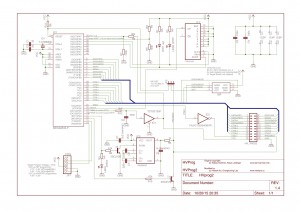
If you are going to use ScratchMonkey exclusively then IC2 74HC165 and its bypass capacitor C3 can be omitted. These parts are for hardware version identification only by Atmel’s firmware.
We recommend you to use a DIP IC socket for IC1 because it enables upgrading/swapping the microcontroller in the future.
The following image is a copy of HVprog2 using PCB sold in our shop.
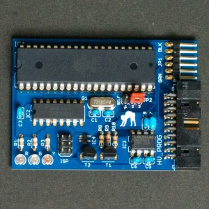
The PCB is designed for thru-hole electronic parts wherever available, and is easy to assemble/solder.
The 6 pins marked JP1 (top right) are for PC connection conveniently aligned for using ubiquitous Sparkfun FTDI breakout board or its clone: If you use 5V version of the breakout then the whole HVprog2 programmer runs in 5V logic, and this is necessary to program in HVSP/PP or TPI. Or using Sparkfun’s 3.3V version then HVprog2 is also in 3.3V logic that matches PDI programming.
The 20 pins marked HV_PROG (bottom right) are for target connections. These pins are ordered to be compatible with those of AVR Dragon. This means we can refer AVR Dragon’s comprehensible documentation for wiring/breadboarding in HVSP/PP.
Software
To burn a software JP2 on HVprog2 board must be set to 1-2 (SELF). Then connecting another ISP programmer to 6 pins marked ISP (near center left) will do the job.
As already stated in the above there are currently two possibilities for HVprog2’s firmware depending on which microcontroller is installed:
- ATmega8535: Atmel’s firmware for original STK500
- ATmegaATmega16/32/64/128 or ATmega164/324/644/1284: ScratchMonkey
Case 1. Atmel’s original firmware is included in any Atmel Studio 4/5/6/7 packages: The name of the binary is STK500.ebn but the file format is not usable with a usual programmer such as avrdude. We need to convert its format “.ebn” to “.hex” using EBN2HEX.exe before burning the binary to the microcontroller (please google and find a download site for EBN2HEX.exe as we cannot find its official webpage). For your information we set ATmega8535’s fuses as S8535C and CKOPT unprogrammed, SPIEN programmed and SUT_CKSEL=”Ext. Crystal/Resonator High Freq; Start-up time: 16K CK + 64ms”.
Case 2. We use ScratchMonkey. The preparation/compile/upload process is the same way described in our previous post.
Target Connections
HVSP/PP. In either Cases, to program in HVSP/PP we can follow the connections to target described in Device Connection Sheets, AVR Dragon’s manual: Refer the connector named HV_PROG.
Note: No need to connect VCC to JTAG as HVprog2 has no such connectors.
ISP. To program in ISP use the ISP connector (JP2 must be set to 2-3).
Note: The VCC pin on HVprog2’s ISP6 connector is always powered by FTDI’s VCC pin.
TPI/PDI. Since HVprog2 is a clone of STK500 or STK500 mod, avrdude requires to be modified as we did in the previous post.
To program a TPI microcontroller two external 510 ohm resistors are required. The HVprog2 board must be powered by 5V version of FTDI breakout board. And use the connection in the following schematic:
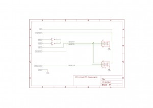
5V, MOSI, MISO, SCK, and GND are located at “ISP” connector (JP2 must be set to 2-3). And VTARGET is at pin 19 of “HV_PROG” connector, RESET5V at pin 5 of “HV_PROG”, and RESET12V is at pin 5 of “ISP” or pin 18 of “HV_PROG” connector. Use signals in TPI connector of the schematic if the reset disable fuse is not programmed. Otherwise use signals in TPI HV connector since high voltage TPI requires the target voltage to be controlled.
To program a PDI microcontroller two external 510 ohm resistors are required. The HVprog2 board must be powered by 3.3V version of FTDI breakout board. And use the connection in the following schematic:
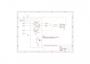
(The parts included in dashdots are unnecessary.)
3V3, MOSI, MISO, SCK, and GND are all located at “ISP” connector (JP2 must be set to 2-3).
