


The post addresses Atmel STK500 starter kit mod as not only HVPP/SP and ISP but also TPI and PDI programmer.
NOTE: This post is nothing to do with GoPro nor Genlock although they are the main topics in this blog.
Introduction
Atmel STK500 is a long-lived product from Year 2001 to now. We consider nowadays most of its users are utilizing it as a simple programmer, and not as starter kit for DIP-package microcontrollers.
STK500 has two microcontrollers ATmega8535L (main) and ATtiny2313V (sub) on its board, and has following features:
- HVPP (High Voltage Parallel Programming) programmer
- HVSP (High Voltage Serial Programming) programmer
- ISP (In-System Programming) programmer
Our mod replaces its main ATmega8535L to a pin-compatible microcontroller that has more flash memory, and removes its sub ATtiny2313V. The latter mod is feasible because since Atmel haven’t offered any new main microcontroller’s firmware after Year 2009 until now sub’s only role of updating main’s firmware is considered to be dead. Once the STK500 board gets a memory-rich microcontroller we can burn an open-source firmware such as ScratchMonkey originally by Matthias Neeracher (modified by Orangkucing Lab) and can also add supports for TPI and PDI.
Hardware Mod
We remove the following four parts from original STK500:
- U200 : ATtiny2313V
- U202 : ATmega8535L
- C200 : Capacitor 47n
- R200 : Resistor 10k
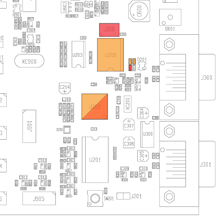
(The figure above is taken from Atmel’s original “STK500 component placement: STK500_asm.pdf”. And also the part numbers are adopted from “Atmel STK500 schematic: STK500.pdf”.)
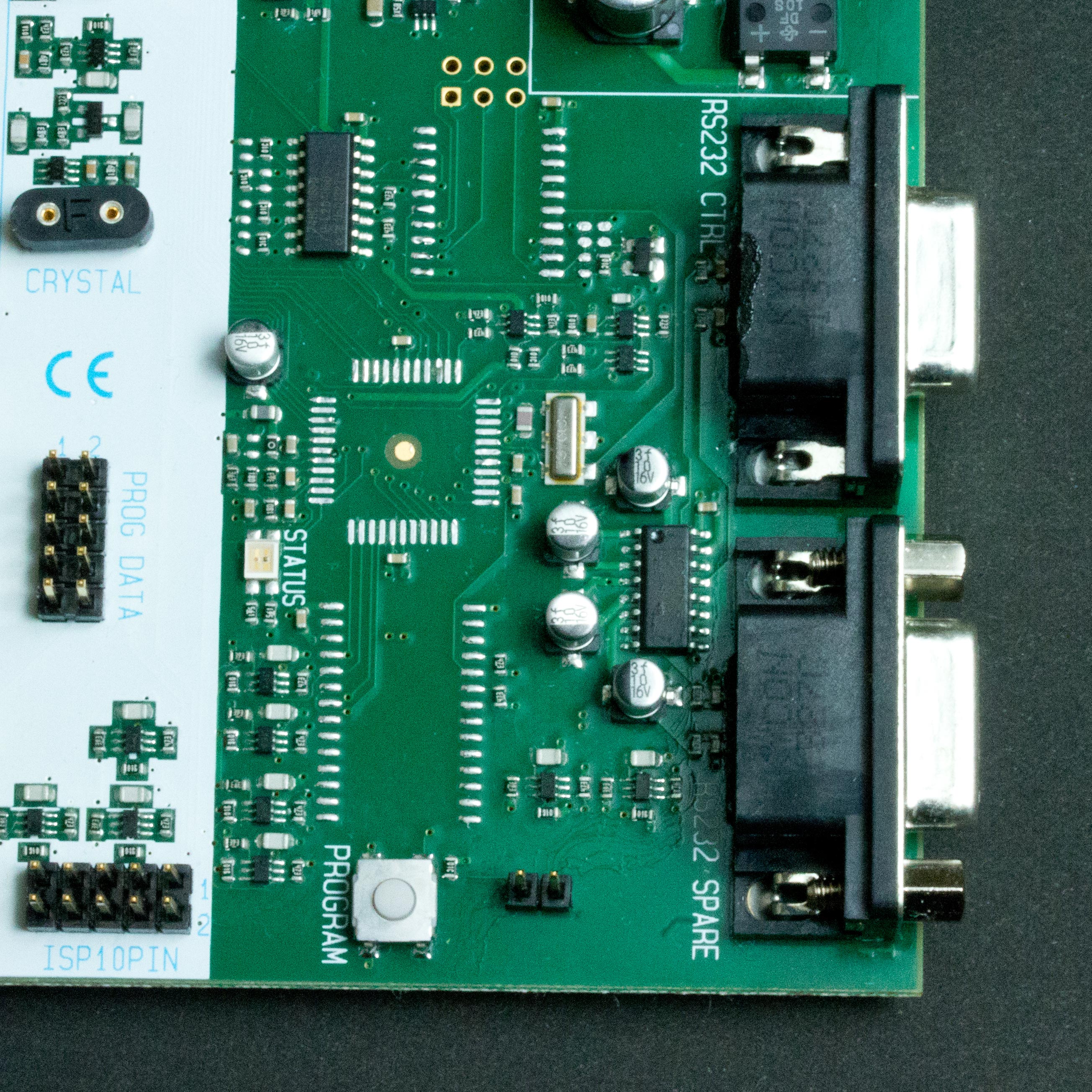
After removing these parts the board looks like the following image:
Then we add the following parts:
- U202 : ATmega1284P
- R213 : Jumper 0ohm (or solder jumper will do)
- J200 : 2×3 header pins
The new microcontroller will be any pin-compatible one to ATmega8535, namely ATmega16/32/64/128 or ATmega164/324/644/1284 families. We used unnecessarily-very-very-high-spec ATmega1284P here because we don’t want to remove/resolder such a delicate SMD chip again in the future.
After soldering these parts STK500 hardware mod has been completed and looks like this:

Software
To burn a firmware to the main microcontroller sit on U202 another ISP programmer is required. We don’t explain here in detail how to upload a firmware or what is an ISP programmer or so since many reader of this post already know these kind of things better than us. 🙂
So just connect another ISP programmer to newly installed J200 pin header and burn the firmware obtained from here (this link is ScratchMonkey’s fork of us but we expect our branch will be pulled and merged to the trunk soon).
If you like to compile the source code using Arduino IDE then its DIP-40 core (“Mighty Core”) is needed. To do this follow the instruction here. After installation of “Mighty Core”, select Tools and board: “Mighty Core”->your microcontroller, clock: “External 7.3728MHz”, pinout: “Standard pinout”; and compile the source code in IDE, then burn the resulted hex-file to your microcontroller.
And for your information we set microcontroller’s fuses to:
- CKDIV8/CKOUT unprogrammed
- SPIEN programmed
- SUT_CKSEL = FSOSC_16KCK_65MS_XOSC_SLOWPWR
Now the STK500 mod board should be recognized as an original Atmel STK500 by Atmel Studio 4/5/6/7 and by avrdude (as stk500v2 for ISP or stk500pp for HVPP or stk500sp for HVSP).
Moreover it is now usable also as a TPI or PDI programmer. The details will be in the next section.
Using STK500 mod as TPI/PDI programmer — Software
Regrettably Atmel Studio doesn’t recognize STK500 mod as a TPI/PDI programmer. The only way is to apply a patch to avrdude’s source code and always use STK500 mod from avrdude in case you need a TPI/PDI programmer.
The patch for avrdude consists of eight (or nine) parts:
Since avrdude has been distributed in many forms/versions the patch is for your reference only and it usually cannot be applied automatically by using the patch tool. So it is normal that you need to edit the stk500v2.c file manually by yourself.
(16 Aug. 2021 Edit: Here is a fork of mariusgreuel’s avrdude v6.3.1.1 whose stk500v2.c has been patched. Also its compiled binary for Windows is in Releases.)
(4 Feb. 2025 Edit: After the repo of official avrdude moved to GitHub @avrdudes I’m very glad to see it has been updated frequently. Here is a fork of @avrdudes’ whose stk500v2.c has been patched.)
The first section (1254,1263) of patch enables PGMTYPE_STK500 for XPROG (TPI and PDI).
The second (3712,3719) and third (3724,3736) sections for calculating flash/eeprom sizes, and the fourth (3795,3801) and fifth (3806,3811) are modified to reporting these sizes to the STK500 mod.
And the rest of patch is for TPI fuse programming that needs “a mystic erase prior to writing”.
Using STK500 mod as TPI/PDI programmer — Connections
After avrdude has been patched you can program any TPI/PDI chips.
To program a TPI microcontroller two external 510 ohm resistors are required. And use the connection in the following schematic:

5V, MOSI, MISO, SCK, and GND are located at J200 ISP6 connector. And VTARGET is at any pin marked “VTG” (jumper “VTARGET” must be set), RESET5V at pin 5 of “PROG DATA”, and RESET12V at “ISP6PIN” or “ISP10PIN” connector. Use signals in TPI connector of the schematic if the reset disable fuse is not programmed. Otherwise use signals in TPI HV connector since high voltage TPI requires the target voltage to be controlled.
To program PDI not only two external 510 ohm resistors but also a quad 5V-tolerant 3-state buffer 74LVX125 are required. And use the connection in the following schematic:

3V3 is at “VADJ” or pin 13 of “EXPAND0” connector (jumper “AREF” must be set), and MOSI, MISO, SCK, and GND are at J200 or “ISP6PIN” or “ISP10PIN”. MOSI_GATE is located at RESET pin of “ISP6PIN” or “ISP10PIN”.
Note: The PDI programming voltage is 3.3V. Since STK500 is in 5V logic some kind of logic level translation is necessary. Thus we tried to use automatic level conversion chips such as MAX3002, GTL2003, TXB0104, and FXMA108 but NONE OF THEM WORKED RELIABLY. It’s a pity we must use a 3-state buffer like 74LVX125. What naive/stupid signals Atmel’s PDI protocol uses!!
Lastly we show example invocations of avrdude:
avrdude -c stk500v2 -p t10 -P /dev/tty.usbXXXXX -vvvv # show detailed transaction and tiny10's signature

avrdude -c stk500v2 -p x128a1 -P /dev/tty.usbXXXXX -U flash:w:hehehe.hex:i # flash hehehe.hex to xmega128a1
where tty.usbXXXXX is the serial port your STK500 mod is connected.
Enjoy!