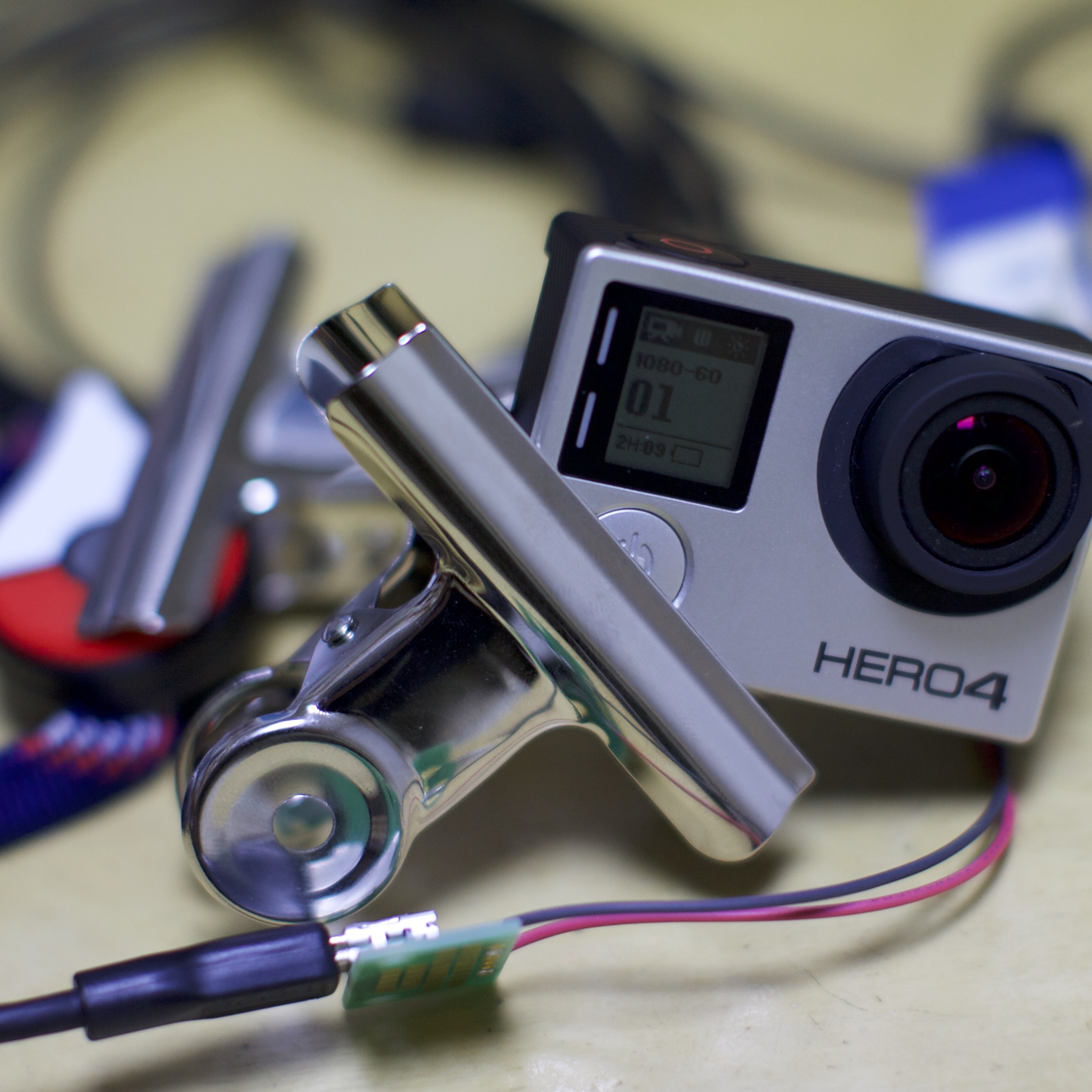


Hero 4 has a new I2C command set incompatible with old Hero 3+ Black. This post gives a demonstration of controlling a standalone Hero 4 camera from Arduino Monitor.
Here is the list of the commands for Hero 4. You can send these commands from your PC’s terminal or Arduino Monitor to MewPro 2 (or MewPro Cable) board or MewPro Iliad through the default UART lines.
Prerequisites
In order to use MewPro 2 as a GoPro Hero 4 controller you need the following hardwares:
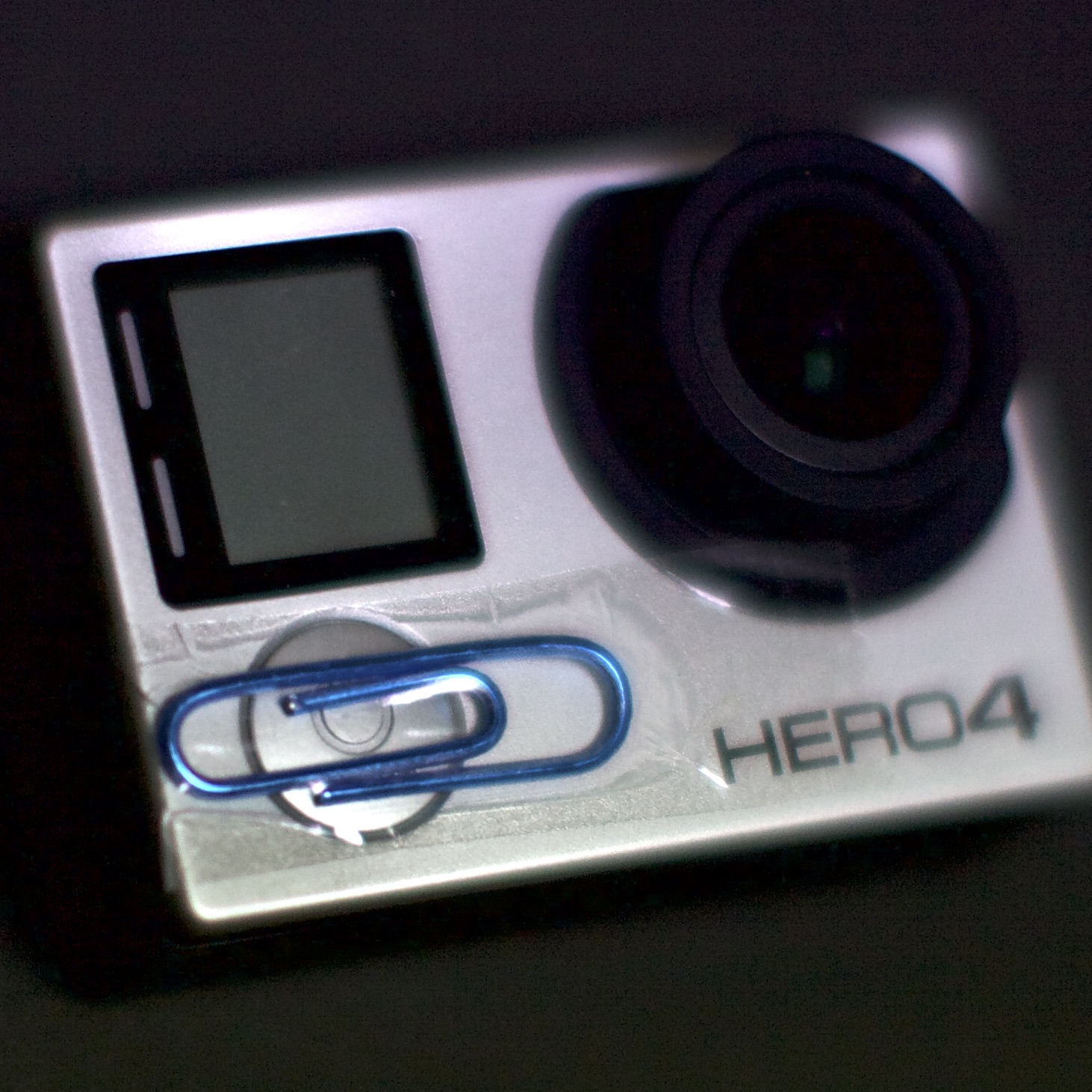
- GoPro Hero 4 Black/Silver
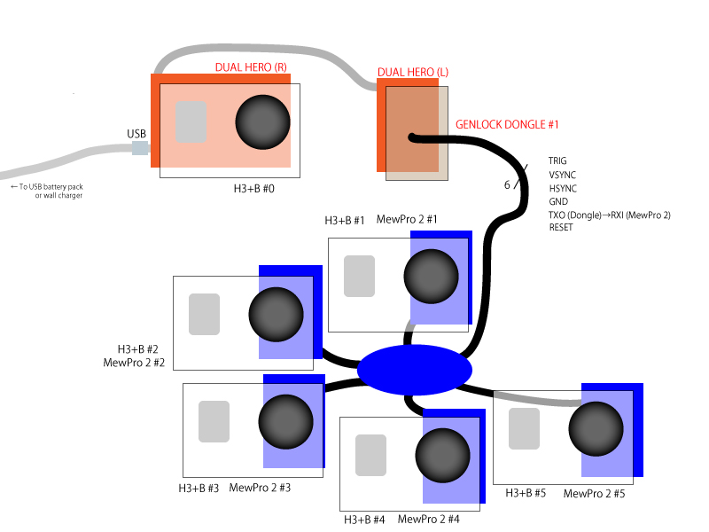
- NOTE: Hero 3+ Black is supported by a different software: Please refer this post.
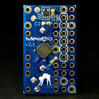
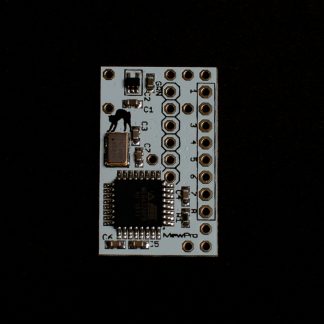
- MewPro 2
- MewPro 2 is ready to use without soldering.
- Arduino Pro Mini Temporary FTDI Header
- If you buy a MewPro 2 from our shop the header is included in the package.
- Sparkfun FTDI Basic Breakout – 3.3V and USB cable
- Use 3.3V version of the breakout board. Any compatible board should work.
Softwares:
MewPro 2 is shipped with optiboot as well as MewPro4 software for genlock installed. If you like to modify/update the software you will need to prepare the following IDE and core. To install each software please refer their documentations.
- Arduino IDE 1.6.12 or newer
- Older versions of Arduino IDE might work but we don’t confirm that.
- ATTiny Core
- 1634, x313, x4, x41, x5, x61, x7, x8 and 828 for Arduino 1.6.x
Lastly grab the MewPro4 application:
- MewPro4 application
- This is an open source software (MIT license). You can modify and distribute it as you like.
Connection
On your PC launch Arduino IDE that was installed as described in the above. In Arduino IDE [File]→[Open...]→ then open MewPro4.ino.
Connect MewPro 2
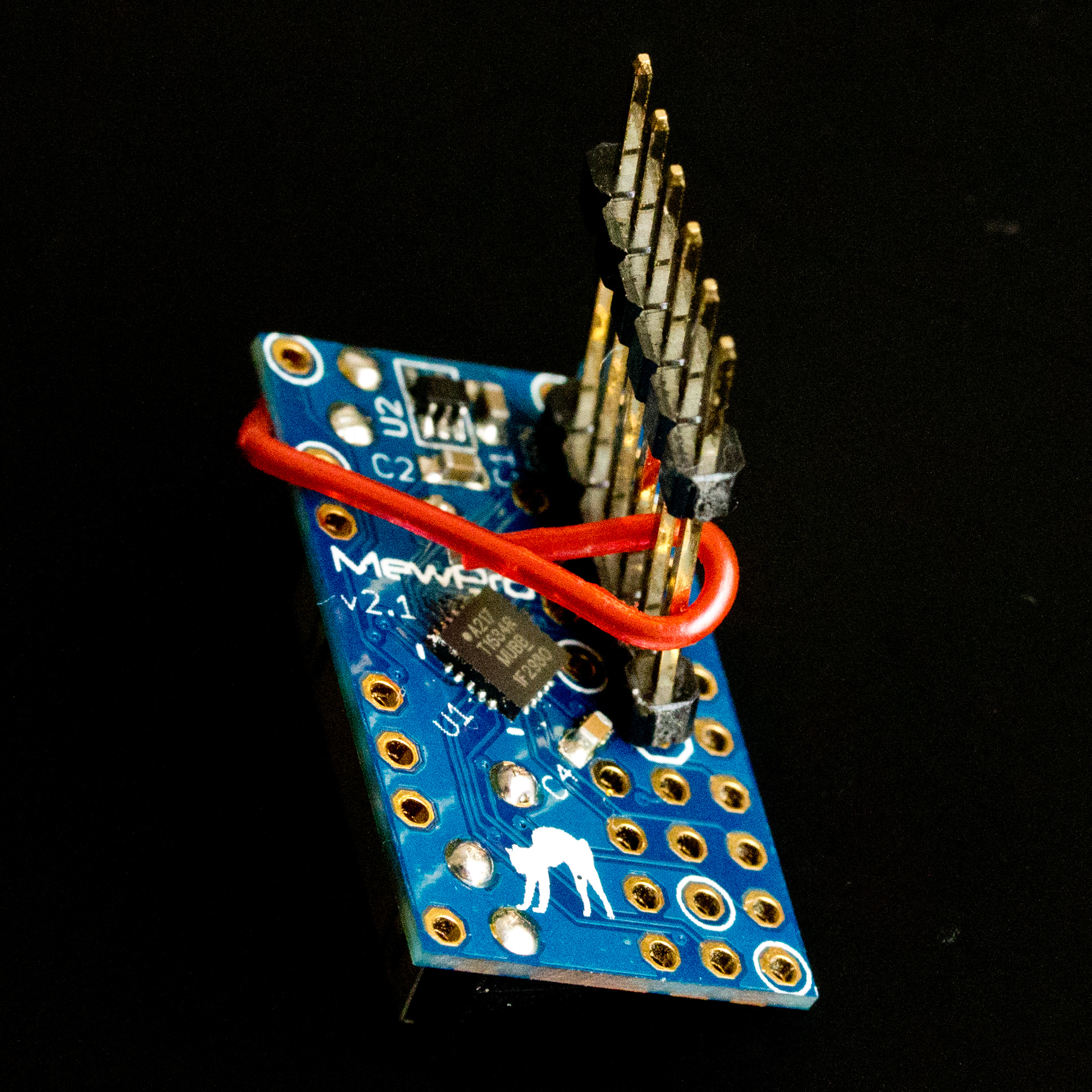
to your PC w/ FTDI board and the temporary header.
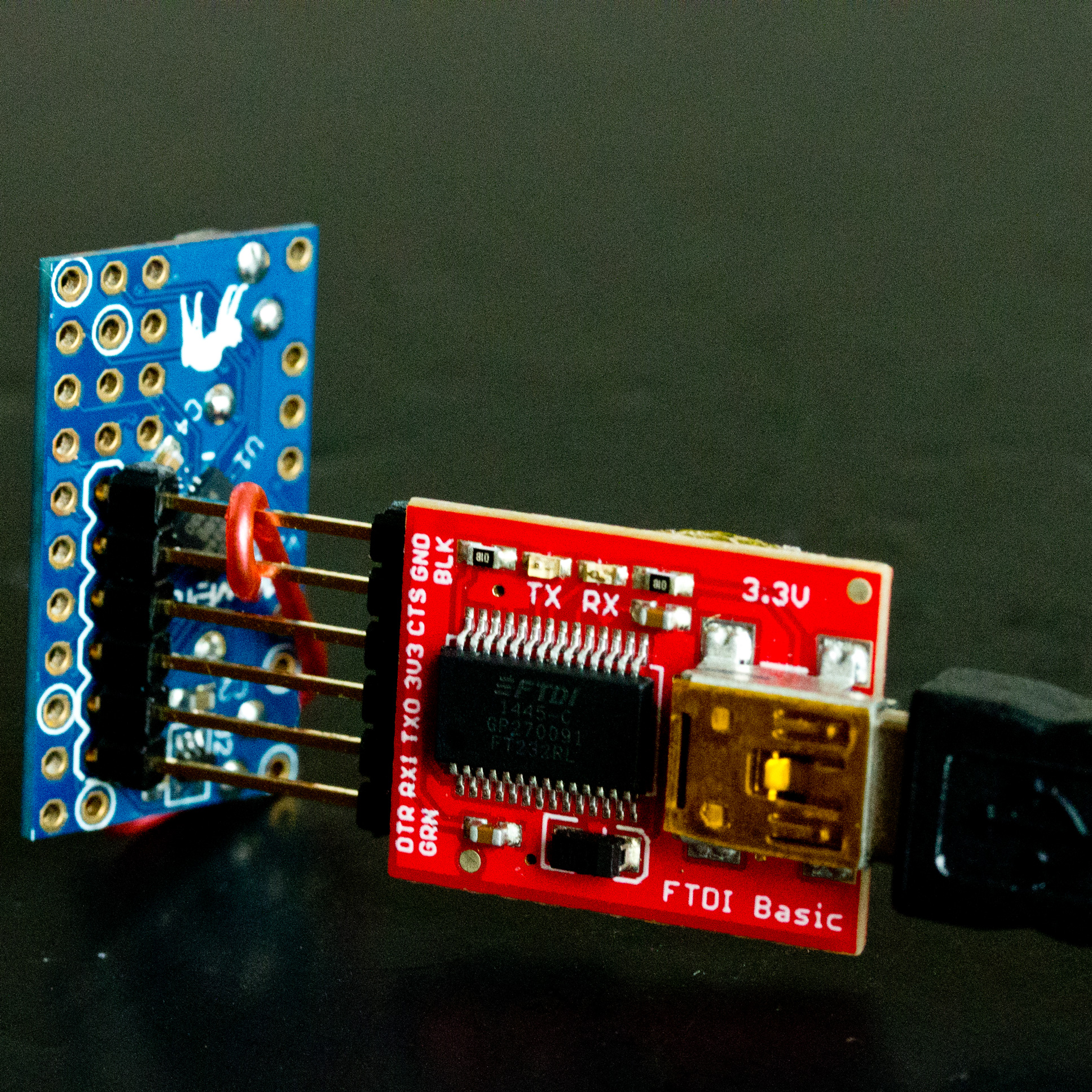
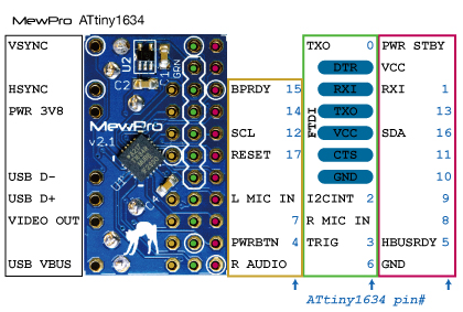
Connecting FTDI please refer the pinout image below:
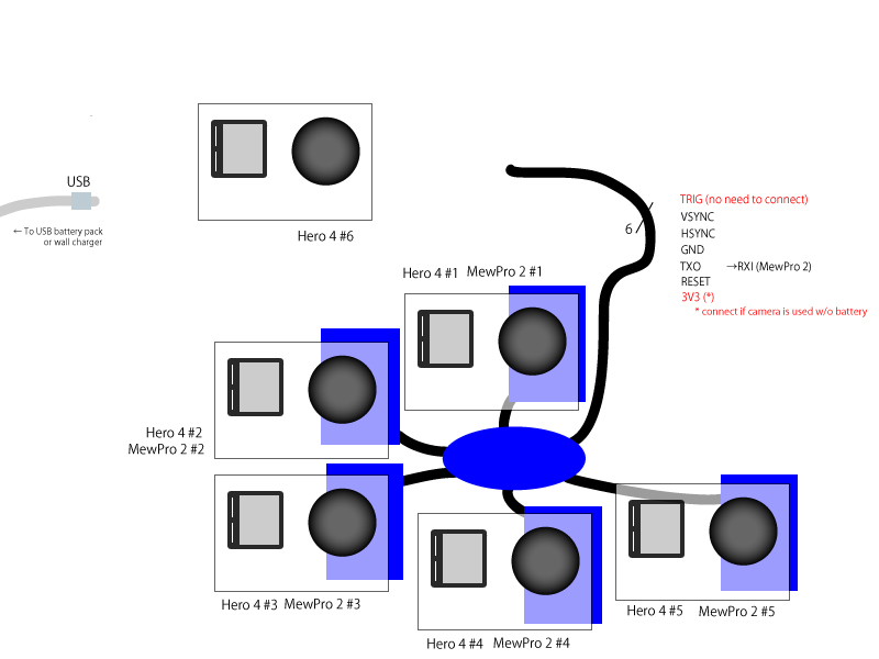
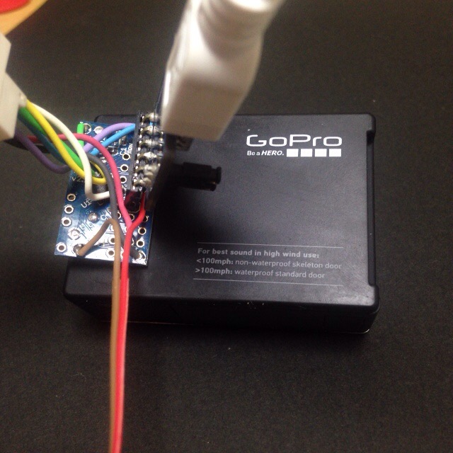
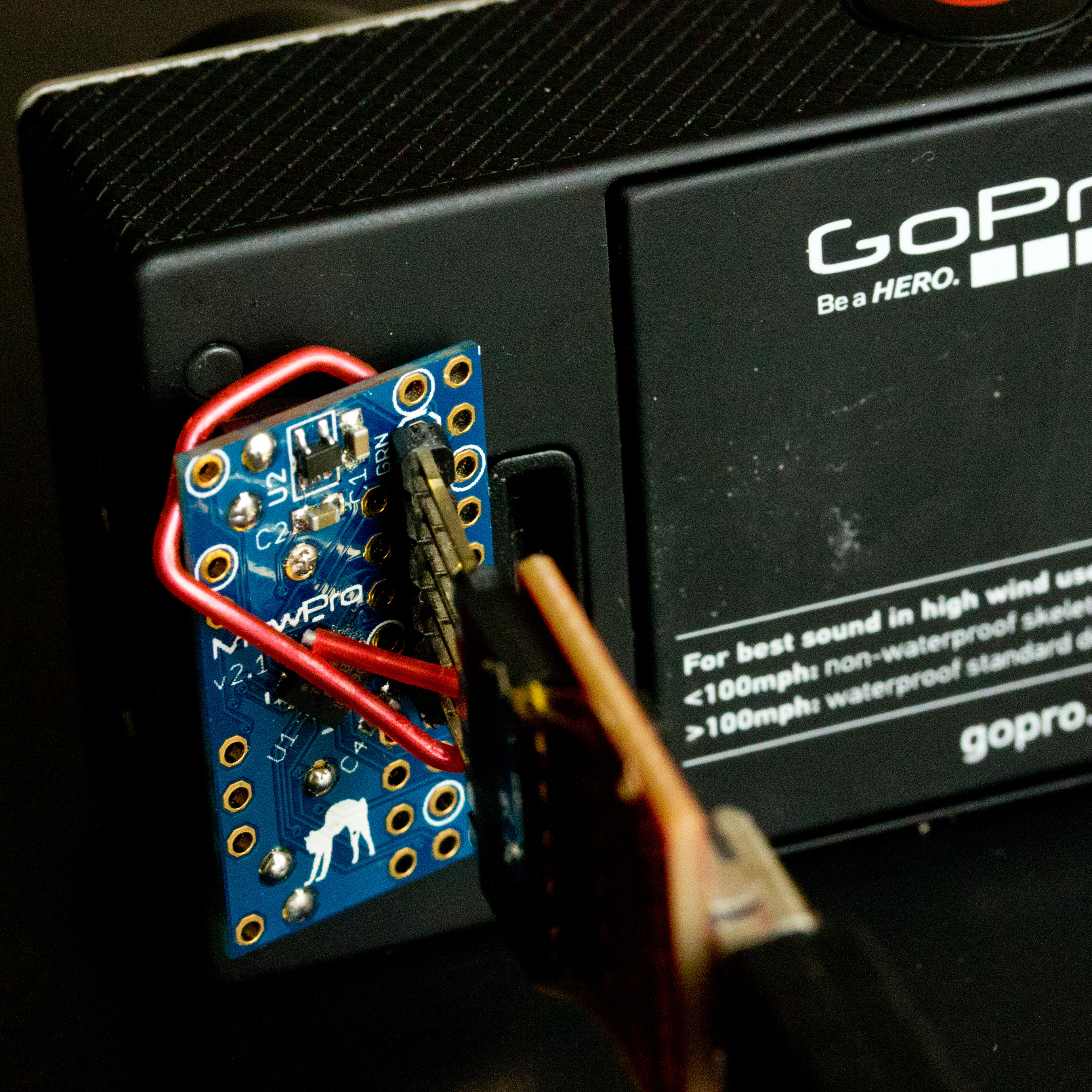
Then connect them to GoPro Hero 4 Black/Silver (The photo below is stolen from our old blog post and connecting to Hero 3+ Black, but I think you will understand where you should connect to. 🙂 ).
In Arduino IDE application, select [Tools]→[Board]→[ATTiny1634 (optiboot)] and [Tools]→[Port]→[(the port where you connected the FTDI cable)]. (B.O.D. and Clock settings are “don’t care” as these values are only effective when you burn a bootloader to the microcontroller by using an ISP programmer.)
The MewPro4 source code is originally targeted to users with multiple cameras, so for standalone usage please edit/change the following line in MewPro.h at line 8
...
// undef if MewPro 2 board is used as standalone
#define USE_GENLOCK
...
to
...
// undef if MewPro 2 board is used as standalone
#undef USE_GENLOCK
...
Now you are ready to compile/upload the source code. Click on “check mark” icon at the top left of Arduino IDE window compiles the code. And “Right arrow” icon at the right next uploads the compiled binary to MewPro 2 board.
#undef USE_TIME_ALARMS in MewPro.h to #define USE_TIME_ALARMS, and also remove two comment-outs ‘//’ located at these two lines:
#include <TimeLib.h> // *** please comment out this line if USE_TIME_ALARMS is not defined ***
#include <TimeAlarms.h> // *** please comment out this line if USE_TIME_ALARMS is not defined ***
Then edit d_TimeAlarms.ino to set your alarms.
Controlling Standalone Hero 4 from Arduino Monitor
Open “Serial Monitor” in Arduino IDE window (click the the top right “magnifier” icon). Set [57600 baud] using the bottom right pulldown, [Newline] the middle pulldown, [Autoscroll] the left box checked.
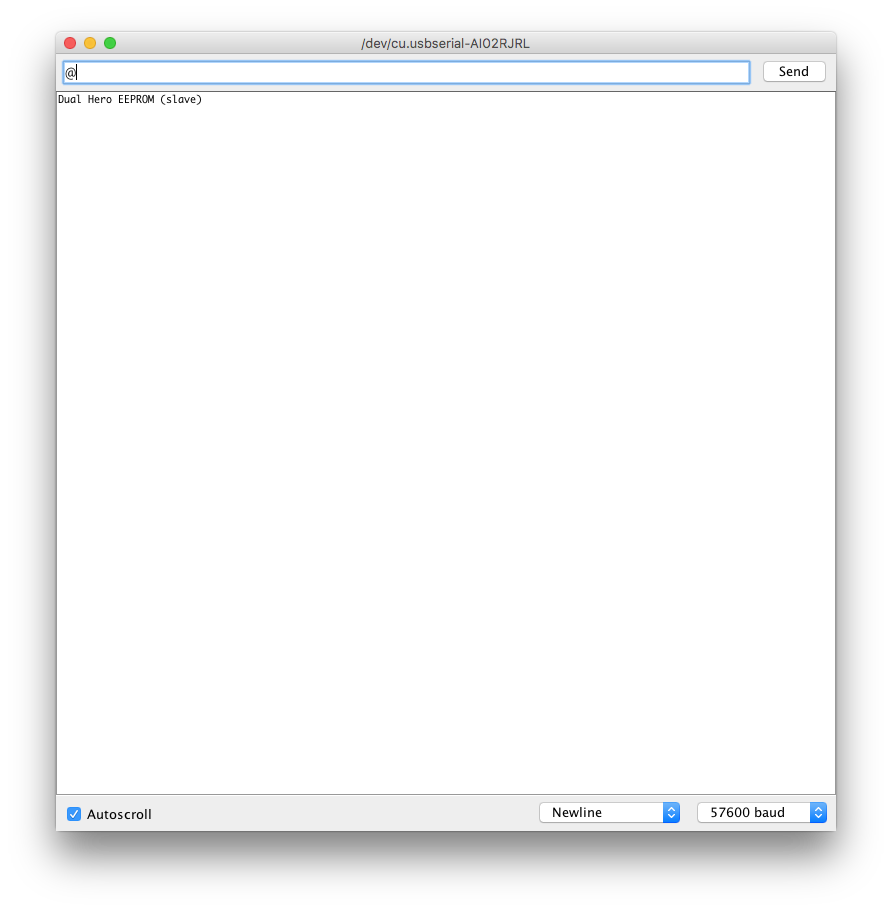
Type ‘@‘ (one letter representing at sign) in the input area of Serial Monitor, and hit return key.
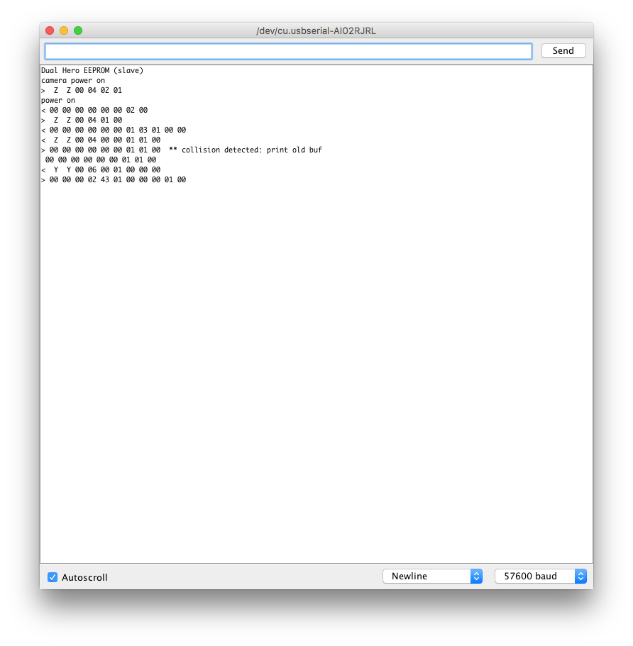
The message “camera power on” is shown and your GoPro Hero 4 turned its power on.
The messages on “Serial Monitor” shows communication details between Arduino and GoPro. And now you can type in any of I2C commands found in “List of GoPro Hero 4 I2C Commands“.
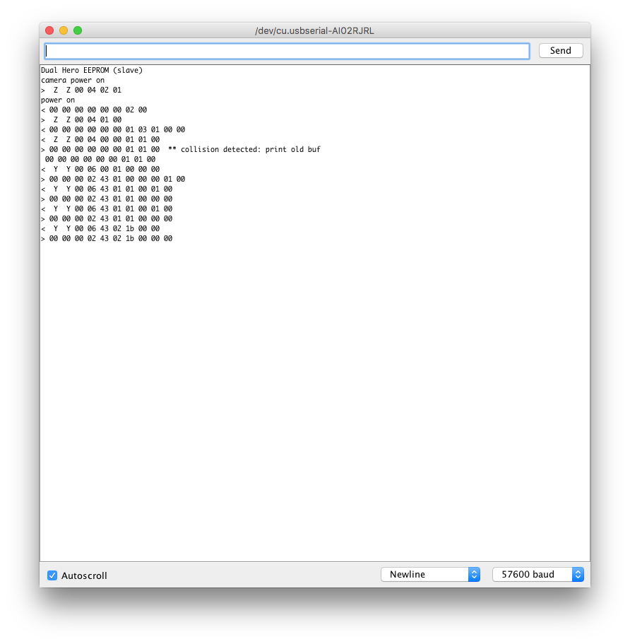
Try typing “YY000101000100” (change camera mode to video) and hit return key unless your camera is in video mode. Then type “YY00021B0000” (and hit return) and “YY00021C0000” (and hit return). (Start recording! Stop recording!!)
If you finished type “ZZ00030101” (and hit return). (This should power off your GoPro Hero 4.)
Enjoy!
Resources
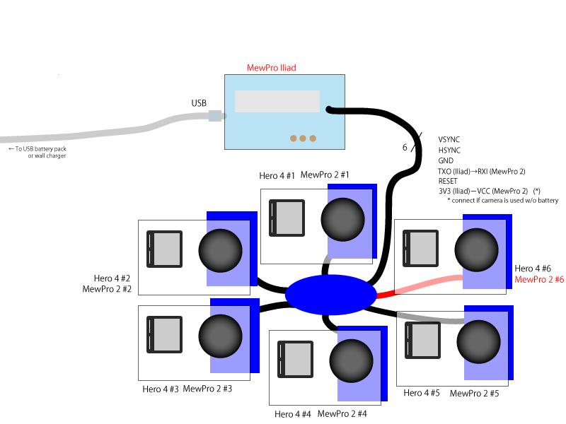
- How To Use MewPro Iliad (only if you are interested in genlocking multiple cameras)
- Purchase MewPro 2
- Schematic Drawing
- Arduino Source Code
- List of GoPro Hero 4 I2C Commands
- Herobus Pinout of GoPro Hero 3+ Black (Hero 4 has the same pinout)