Posted on Leave a comment

No Master Configuration For Genlocking

A PC controlled genlock system support is added to Dongle’s source code.

For genlock rigs we’ve offered two configurations, namely

  1. Single Dongle configuration
  2. Double Dongle configuration

and these are described in this post. The latter is usable with PC by connecting MewPro #0 to FTDI serial USB breakout and by sending commands from its console.

Shāndōng University – Virginia Tech researchers use a double dongle configuration, as I know so far, and also use a PC that is connected to MewPro #0 in order to control the whole system. (For their recent progress, a blog post is here: Matt Bender, Mincan Cao, Yu Wei, Shaoxu Xing “Tracking of Fiducial Markers for Bat Flight Motion Capture Experiments)

To control the whole system from PC, today we added support for

  • 3. no master configuration.

Control everything from PC. No master camera.

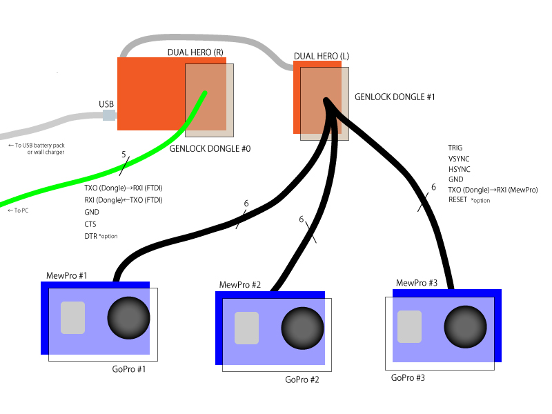
(DTR connection between Dongle #0 and FTDI is for resetting Dongle #0 when uploading a sketch to the dongle or opening the Arduino Monitor in PC.)

As you can see this is the same to the single dongle configuration but GoPro #0 is replaced by Genlock Dongle #0 connected to PC through FTDI serial USB breakout board.

The no master configuration is completely symmetric and everything is PC controllable but there is no master camera that you might be accustomed to push mode/shutter buttons or to browse through menus on LCD.

How To Use No Master Configuration

You should follow the instructions for single dongle configuration first. And don’t forget to prepare/buy one more Genlock Dongle for Genlock Dongle #0 in the figure above.

You must update the dongles with the latest version of Dongle source code that supports no master configuration. It is always available at the GitHub repo.

For dongles the initial value of bool debug and the directive UART_RECEIVER_DISABLE should be set as follows:

bool debug UART_RECEIVER_DISABLE
Dongle #0 true or false #undef
Dongle #1 false #undef or #define

(Bold face is the default in the GitHub source code.)

In this configuration usable commands from PC are those which are listed in the I2C command list and its label contains _BACPAC_.

Example:

  • SH1 start recording/shutter
  • SH0 stop recording
  • CM1 change mode to camera
  • VV0A change video resolution to 720p Super
  • etc., etc.

The dongle also suports two more commands:

  • @ power on
  • & toggle debug output

Enjoy!

Posted on Leave a comment

New firmware 3.03 for H3+B

Just a quick note about the firmware for HERO3+ Black Edition v03.03 (September 2, 2015). This firmware works fine with MewPros.

Note to Genlock Dongle users: Dongle’s software also needs update as it emulates a version of camera hardware; both the master camera and the slave camera (or dongle) must have the same version. The source code in GitHub is now modified to use with the current version 3.03 so please download and install it to your dongle.

Posted on Leave a comment

How To Make MewPro Cable

This post is for those who bought our MewPro Cable products WITHOUT cable (i.e. for customers of plug-only MewPro Cable) and to explain how to solder your genlocking units.

For genlocking the wires among plugs and Dongle must be soldered by yourself. It shouldn’t be so difficult task nevertheless the through holes are really small. But if you like everything to be inside of the plug enclosure then it never be easy or you must be a true wizard/witch of soldering.


Solder Wires to PCB

MewPro Cable is basically a reduced/shrinked version of MewPro 2 board. So please refer the post “How To Use MewPro Genlock Dongle”, too.

Wires to the board in the plug are shown as in the following figure.

Wires of MewPro Cable

Use smaller through holes for soldering as larger holes will be needed for future update of the firmware.

plug-assemble-board

Before soldering these wires to both plug and Dongle, don’t forget to thread a strain relief (the black, cylindrical part with legs in the above photo).

Plug casing can be closed as in the following pictures.

Assemble the bottom half
1. Assemble the bottom half

Assemble the top casing
2. Assemble the reminder

Note: If once the lid clicked closed it’s impossible to open the cover of plug again without breaking black plastic tabs.


Updating Firmware

MewPro Cables are shipped with the genlock firmware installed. But in future possible firmware updates by yourself may be preferred.

In order to upload a software to ATtiny1634 microcontroller, you’ll need some temporary testing wires, which we use is shown below for example, as well as a Sparkfun FTDI Basic Breakout – 3.3V (or its clone).

Sanhayato TTW-200 Testing Wires

Sanhayato TTW-200 can be purchased in Japan only from this site.

These wires can be used as in the following.

plug-upload

Connections between MewPro and FTDI are:

MewPro FTDI
GND GND
3V3 3V3
RXI TXD
TXO RXD
GRN DTR

Resources