


This post is for those who bought our MewPro Cable products WITHOUT cable (i.e. for customers of plug-only MewPro Cable) and to explain how to solder your genlocking units.
For genlocking the wires among plugs and Dongle must be soldered by yourself. It shouldn’t be so difficult task nevertheless the through holes are really small. But if you like everything to be inside of the plug enclosure then it never be easy or you must be a true wizard/witch of soldering.
Solder Wires to PCB
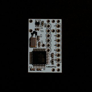
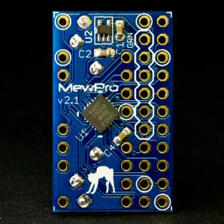
MewPro Cable is basically a reduced/shrinked version of MewPro 2 board. So please refer the post “How To Use MewPro Genlock Dongle”, too.
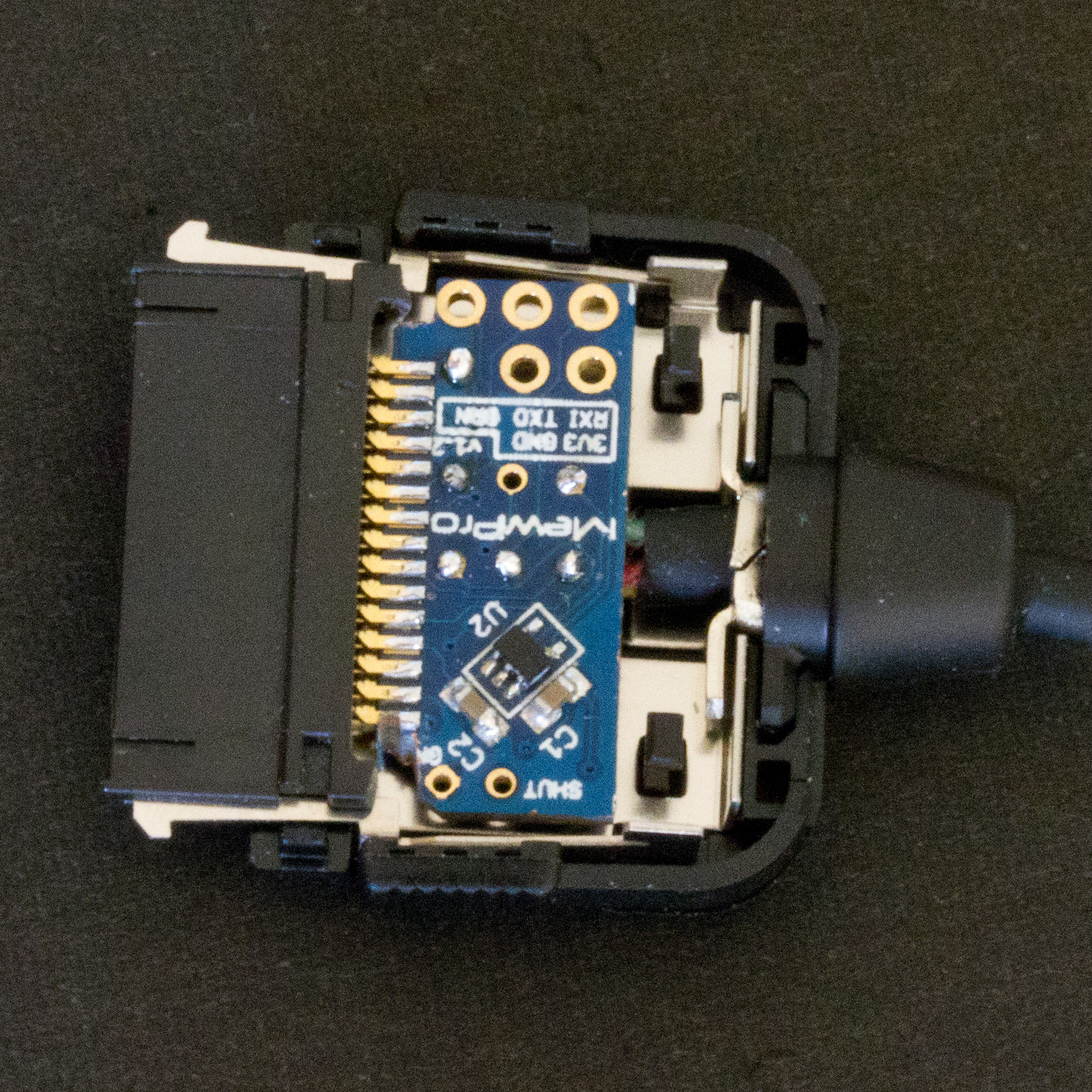
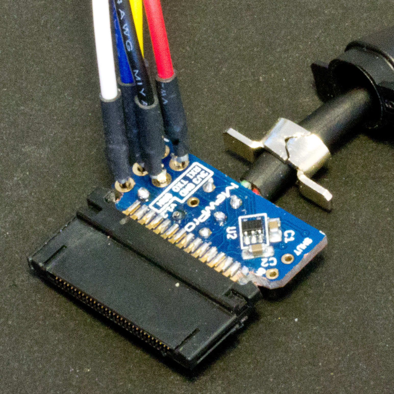
Wires to the board in the plug are shown as in the following figure.
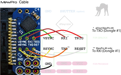
Use smaller through holes for soldering as larger holes will be needed for future update of the firmware.
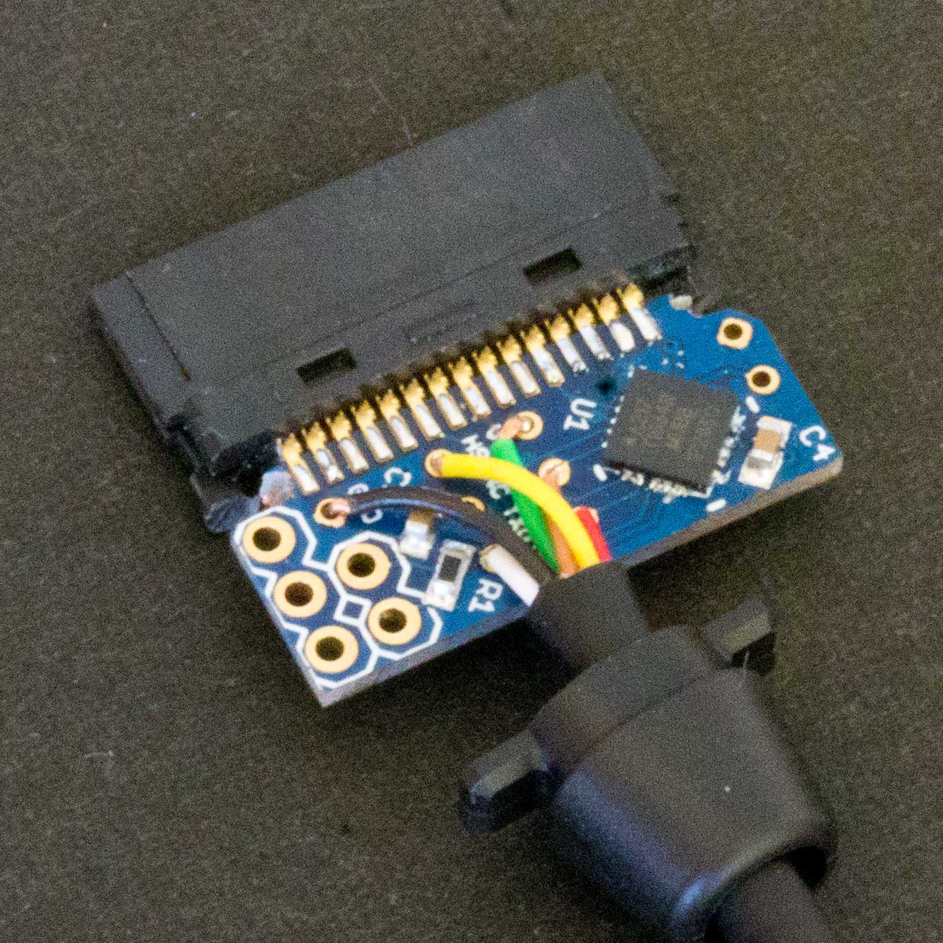
Before soldering these wires to both plug and Dongle, don’t forget to thread a strain relief (the black, cylindrical part with legs in the above photo).
Plug casing can be closed as in the following pictures.
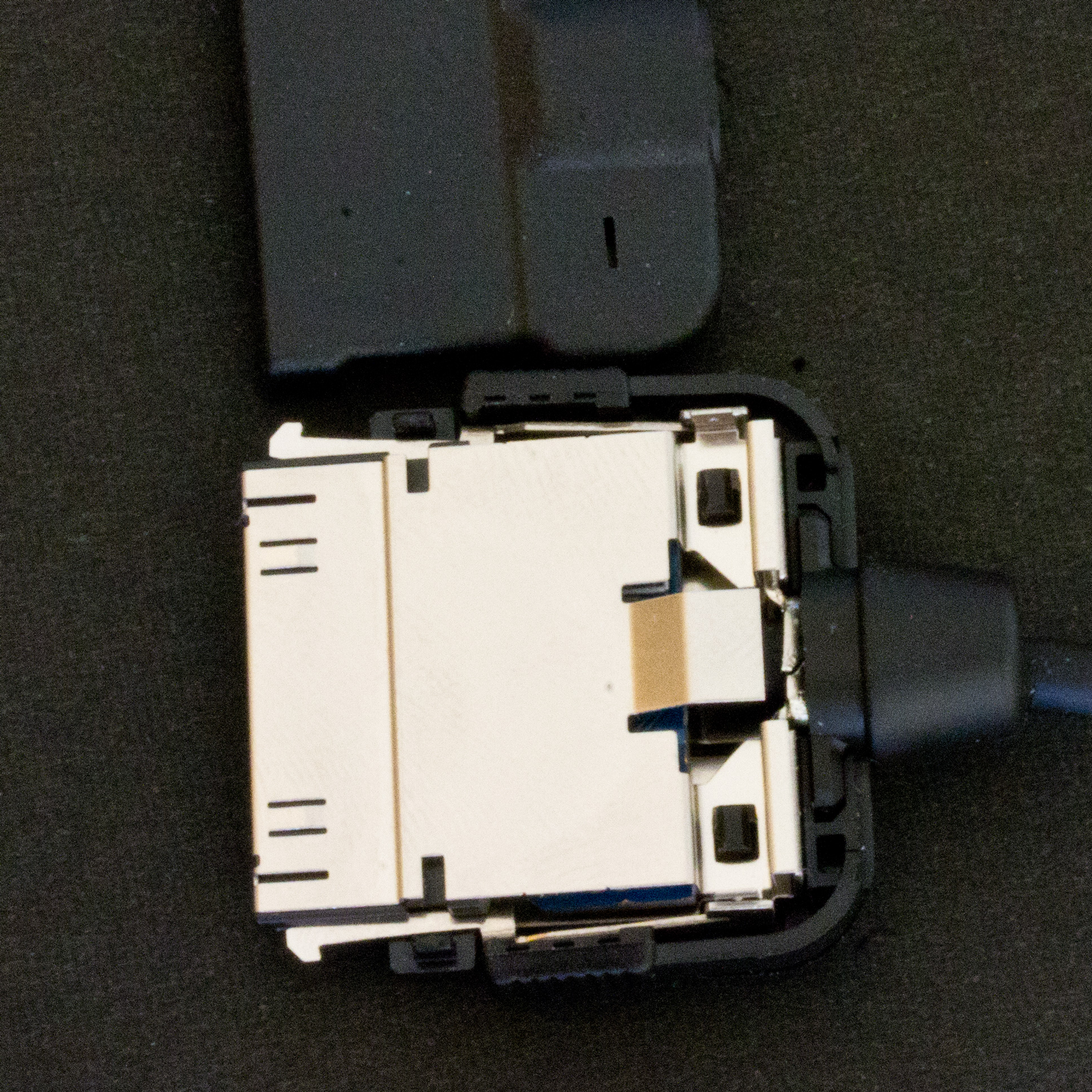
Note: If once the lid clicked closed it’s impossible to open the cover of plug again without breaking black plastic tabs.
Updating Firmware
MewPro Cables are shipped with the genlock firmware installed. But in future possible firmware updates by yourself may be preferred.
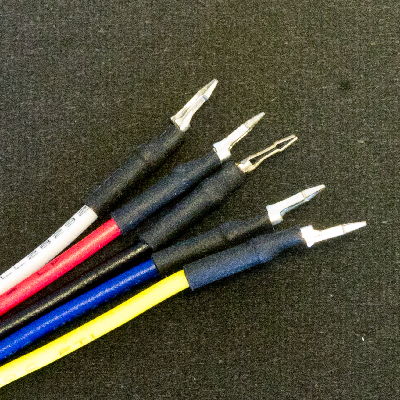
In order to upload a software to ATtiny1634 microcontroller, you’ll need some temporary testing wires, which we use is shown below for example, as well as a Sparkfun FTDI Basic Breakout – 3.3V (or its clone).
Sanhayato TTW-200 can be purchased in Japan only from this site.
These wires can be used as in the following.
Connections between MewPro and FTDI are:
| MewPro | FTDI |
|---|---|
| GND | GND |
| 3V3 | 3V3 |
| RXI | TXD |
| TXO | RXD |
| GRN | DTR |
Resources
- How To Use MewPro Genlock Dongle
- How To Use MewPro 2 and Application MewPro 2 and MewPro Cable are basically the same hardware.