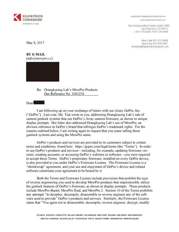
(The date “8 May” written in received letter is wrong. We received this letter today. Also we notice that there is a strange word “gunlock” in the letter.)
UPDATE 24 May 2017: Our attorney sent a reply to GoPro.
UPDATE 18 May 2017: Dead line for replying the mail has been extended to 24 May 2017. We are consulting a lawyer now.
UPDATE 12 May 2017: Signature is painted orange because the sender requested to do so.
In this post we explain how to connect wires to MewPro Bastet.
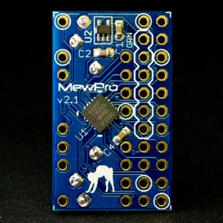
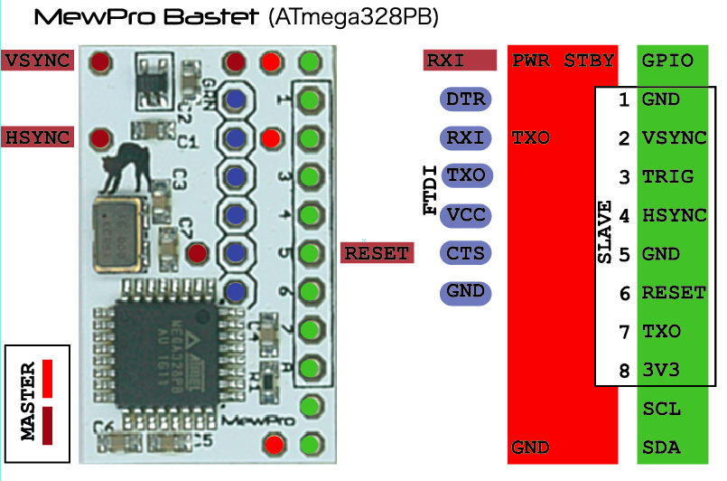
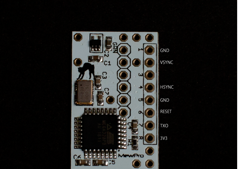
MewPro Bastet Pinout
The following picture shows the pinout of Bastet.
There are pins for master, slave(s), and programming (FTDI Breakout Board) denoted by color brown or red, green, and blue, respectively.
Software For Master MewPro 2 board
The MewPro 2 board (MewPro #0 in this diagram) attached to the master camera (GoPro #0) must have MewPro 4 master firmware installed.
To install the master firmware please follow the ordinary steps described in this post with changing the following two lines in the MewPro4 source code MewPro.h at lines 6 and 9 from:
boolean debug = true;
#undef  BASTET_MASTER
to
boolean debug = false;
#define BASTET_MASTER
respectively, before compiling and uploading to the board.
Note1: Slave MewPro 2’s should have the default firmware without any modification to the MewPro4 source code.
Note2: If you like to use Bastet in the good old housing that came with GoPro’s discontinued Dual Hero system for Hero 3+ Black then it’s better to modify the 17th line in `MewPro.h` as `#define DUAL_HERO_ORIENTATION`. Uploading this to slave MewPro board(s) will enable the slave camera to be upside down regardless of master’s orientation setting.*
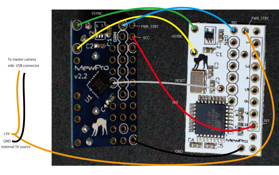
Connect To Master
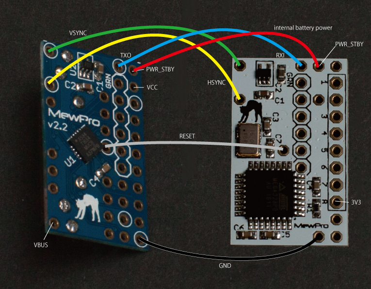
Firstly, serial line, GND, and sync signals must be connected as follows:
GND and sync signals
signal name
MewPro 2 (master)
Bastet
Serial
TXO
—
RXI
VSYNC
VSYNC
—
VSYNC
HSYNC
HSYNC
—
HSYNC
GND
GND
—
GND
Next, there are three cases to feed power to the master camera:
Master camera is powered by internal battery.
Master camera is without internal battery and powered by external 5V at the herobus connector.
Master camera is without internal battery and powered by external 5V at the side USB connector.
[Case 1: Master camera is powered by internal battery]
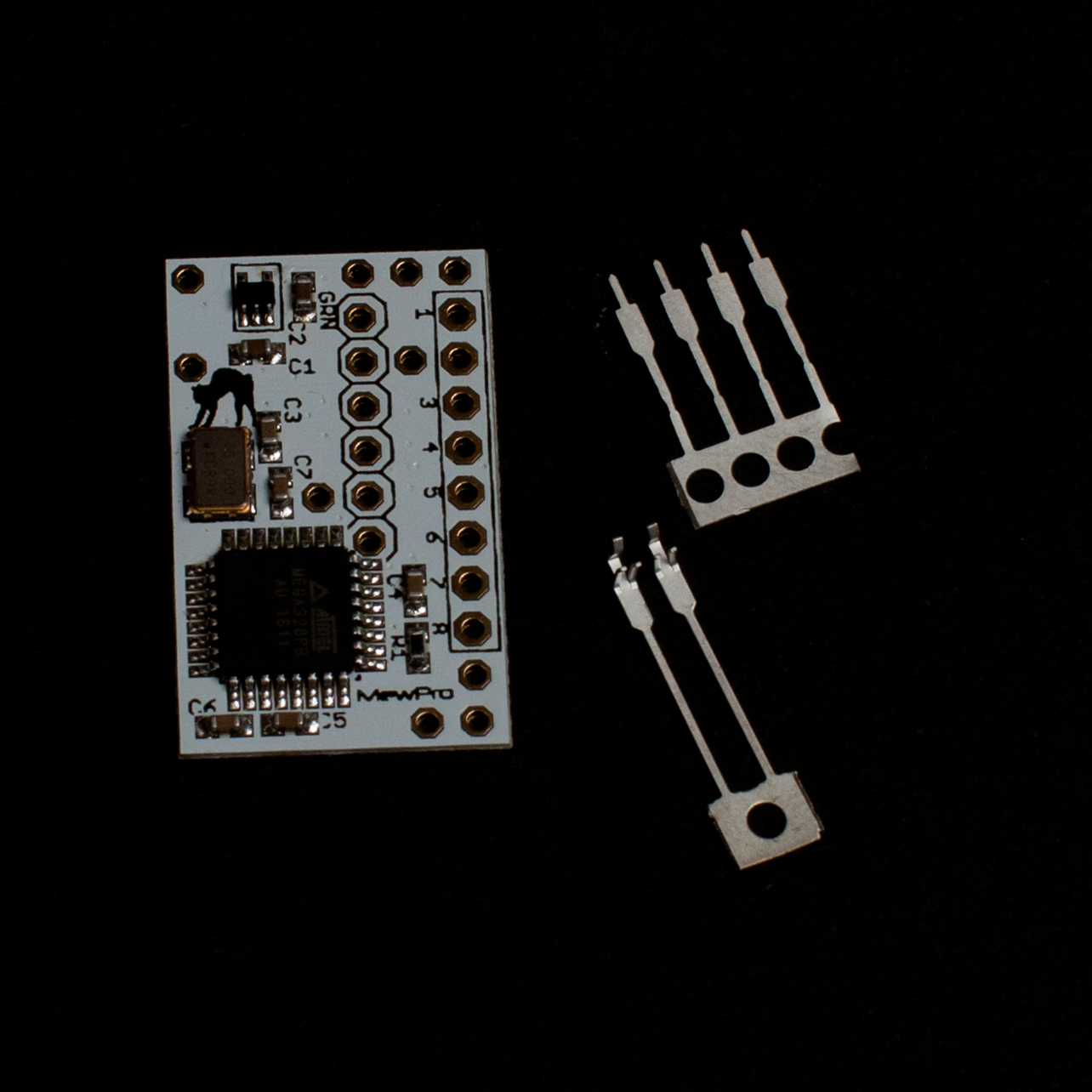
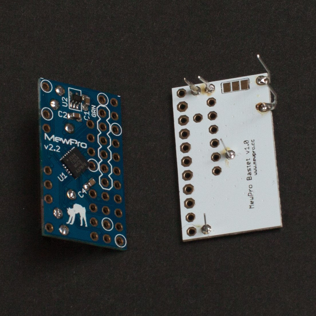
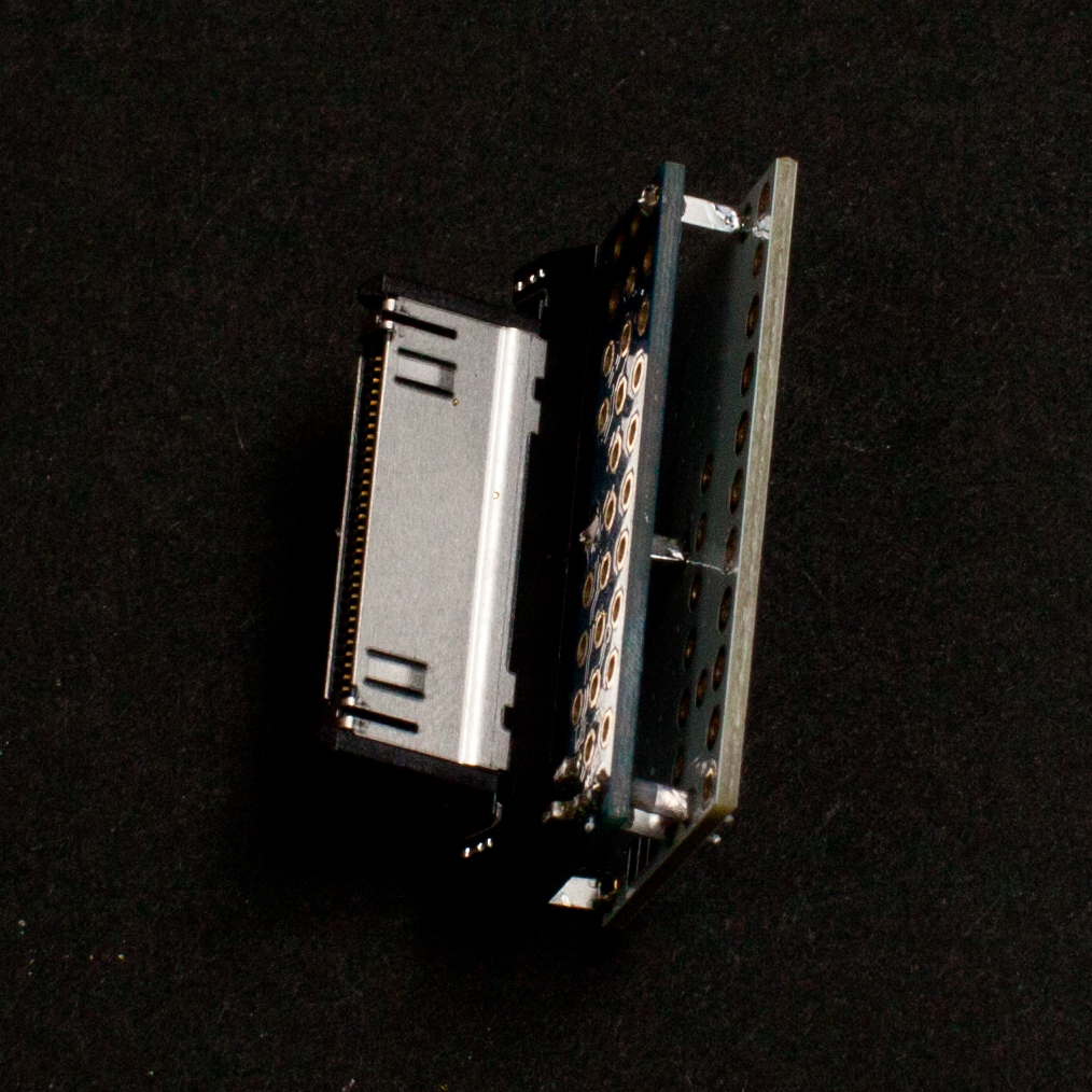
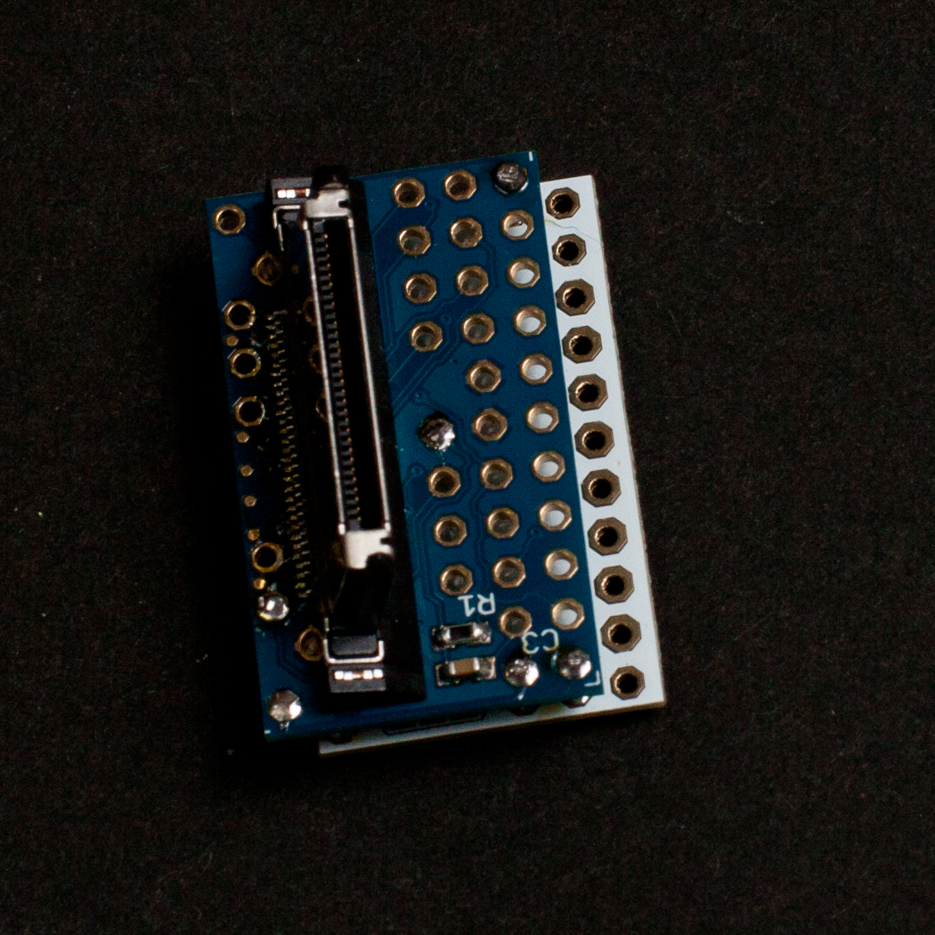
The pins for master are aligned with those of MewPro 2 board. So you can put Bastet on top of MewPro 2 using lead frames or tin plated wires as in the following photos. (If you purchase Bastet from our shop then these lead frames are included.)
Bastet and lead framesLead frames soldered
The above is our recommended way of connecting to the master. However, there might be cases that there are no room for Bastet board on top of MewPro 2 in your rig or cases of using MewPro Cable as a master. If your situation dosn’t allow placing Bastet on top of MewPro 2 board then please refer the following table and image.
Master camera is powered by the internal battery
voltage rail
MewPro 2 (master)
Bastet
powered by
internal battery
internal battery
unregulated 3V8
PWRSTBY
—
PWR STBY
3V3
not connected
not connected (*)
5V
not connected
not connected
Note *: Bastet outputs regulated 3V3 for slave MewPros.
Camera is powered by the internal battery
.
[Case 2: Master camera is without internal battery and powered by external 5V at the herobus connector]
If you like to power the master camera through the herobus connector please refer the following table and image.
Master camera is without internal battery and is fed through the herobus connector
voltage rail
MewPro 2 (master)
Bastet
powered by
Bastet
external 5V
unregulated 3V8
not connected
DON’T CONNECT TWO PWRSTBY PINS!
not connected
3V3
VCC
—
3V3
5V
VBUS
—
PWR STBY (**)
Note **: Never connect 5V to MewPro 2’s PWRSTBY. To do so will instantly ruin your camera.
[Case 3: Master camera is without internal battery and powered by external 5V at the side USB connector]
If you like to power the master camera through the side USB connector please refer the following table and image.
Master camera is without internal battery and is fed through the side USB connector
voltage rail
MewPro 2 (master)
Bastet
powered by
Bastet
external 5V
unregulated 3V8
not connected
DON’T CONNECT TWO PWRSTBY PINS!
not connected
3V3
VCC
—
3V3
5V
not connected
PWR STBY (**)
Note **: Never connect 5V to MewPro 2’s PWRSTBY. To do so will instantly ruin your camera.
Connect To Slaves
Connections between Bastet and slave MewPro 2’s are the same to those between Iliad and MewPro 2’s (Note: In Iliad system all MewPro 2’s are slaves). You can use our Stackable Hub with Buffer or simply connect thru holes by wire or make something like a DIY octopus cable to connect Bastet and slaves.
Moreover, Bastet’s thru holes for 6-core cable to slaves are aligned as the same to Iliad.
a) It is necessary to push buttons of master camera SLOWLY. If there is not enough period between two button presses then the master camera fails to notify some events to Bastet through master MewPro 2 board. This is GoPro’s firmware limitation so don’t blame MewPro and Bastet. The failure can be resulted in video/photo mode inconsistency among cameras and, moreover, incompatible sync signals can make cameras freeze. And also, please WAIT 8 SECONDS AFTER POWER ON because camera booting up takes this long.
b) Camera’s “low light” option is not usable with external sync. Thus, it is set to off by MewPro 2’s default, however, you can also accidentally enable the option. So always take care camera’s LCD is not showing you the “low light” icon.
c) After assembling/connecting Bastet, MewPros, and cameras it is normal that the system becomes unstable. In order to overcome this situation Bastet resets all the MewPro 2 boards every time when it receives power off command from the master.
This behavior enables us to reset the whole system by following the steps below:
Reset Procedure of Bastet System
[Step 1: Slave OFF] By long pressing the camera’s mode button, power off each slave camera if it is on. (Even when some cameras are frozen, pressing its mode button for six seconds makes it power off.)
[Step 2: Master OFF] Master camera’s power must be off at last.
[Step 3: Master ON] After all the cameras are power off, power on the master camera by using its mode button or wifi RC. To do this also power on all the other cameras.
[Step 4] If something strange happens then go to Step 1.
MewPro Bastet is a small device that enables us to control/genlock GoPro Hero 4 cameras. Unlike our monolithic MewPro Iliad, it simply listens broadcast by the master and provides sync signals for all of cameras while recording.
MewPro Bastet is ready to purchase in our shop, however, its product description is still under construction (I’m now editing it…).
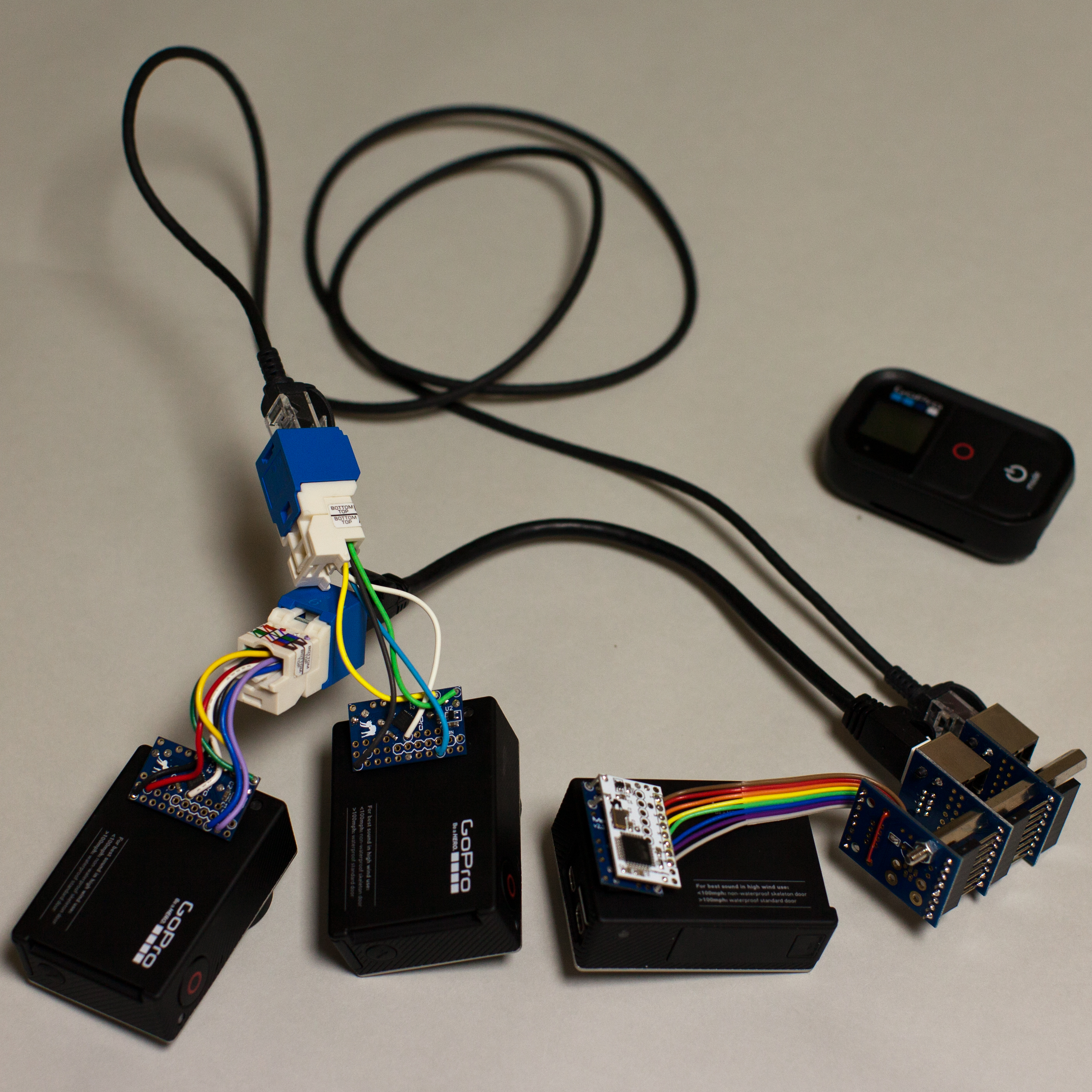
Demo
The following video shows the three Hero 4s are synced and controled by Wi-Fi RC. (Power on — change mode -(video)- start recording — stop -(photo)- take a photo — power off.)
To make the footage we used:
3 GoPro Hero 4 Black (one master and two slaves)
3 MewPro 2
1 MewPro Bastet
(cables and plugs/receptacles)
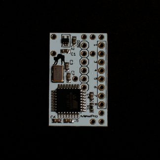
The white PCB is Bastet, the blue PCBs are MewPro 2s.
In the photo above you’ll also find bulky RJ45 Ethernet receptacles or “Stackable Hub with Buffer”, however, these parts are not always necessary for syncing cameras in, for example, weight restricted environments such as shooting videos from the sky.
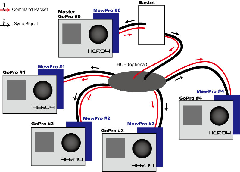
How It Works
In Fig. 1 the number of GoPro Hero 4 cameras is five for example. Of course, any number of cameras can be synced in this way.
MewPro Bastet is put between the master camera (GoPro #0 in Fig. 1) and the slaves (GoPro #1, #2, #3, #4 in Fig. 1). It wiretaps the command packets that the master sends to the slaves. It understands all commands and changes its internal states accordingly. And once master’s shutter button is depressed then it begins to generate sync signals (VSYNC/HSYNC).
Fig. 1
In the diagram above “Hub (optional)” can be either solder joints of wires or our Stackable Hub with Buffer or some kind of DIY octopus cable or a strip board with 6 lines in parallel or something. We only offer a solution with Stackable Hub with Buffer but you can do it yourself in place of this in order to reduce the space.
Comparison Table Between Iliad and Bastet
For your information the following is a brief comparison table between Iliad and Bastet.
Iliad
Bastet
Size
larger than Hero 4
equal to MewPro 2
MCU
ATmega2560
ATmega328PB
LCD
16 x 2
none
Switches
3
0
Infra Red
1
0
Wi-Fi
no
master camera (*)
Software
MewPro_Iliad
MewPro_Iliad
MewPro 2
all slave
all slave but one master (**)
Note *: All the cameras are controlled by the master regardless of whether the change is made by using Wi-Fi or master camera’s button press.
Note **: The MewPro 2 board attached to the master GoPro must have MewPro 4 firmware that is compiled with #define BASTET_MASTER compiler directive. While other boards should have the default MewPro 4 firmware.
How To Use MewPro Bastet
In the next blog post we’ll explain how to connect wires between Bastet and each MewPro boards.
Hero 4 has a new I2C command set incompatible with old Hero 3+ Black. This post gives a demonstration of controlling a standalone Hero 4 camera from Arduino Monitor.
Here is the list of the commands for Hero 4. You can send these commands from your PC’s terminal or Arduino Monitor to MewPro 2 (or MewPro Cable) board or MewPro Iliad through the default UART lines.
Prerequisites
In order to use MewPro 2 as a GoPro Hero 4 controller you need the following hardwares:
GoPro Hero 4 Black/Silver
NOTE: Hero 3+ Black is supported by a different software: Please refer this post.
Use 3.3V version of the breakout board. Any compatible board should work.
Softwares:
MewPro 2 is shipped with optiboot as well as MewPro4 software for genlock installed. If you like to modify/update the software you will need to prepare the following IDE and core. To install each software please refer their documentations.
This is an open source software (MIT license). You can modify and distribute it as you like.
Connection
On your PC launch Arduino IDE that was installed as described in the above. In Arduino IDE [File]→[Open...]→ then open MewPro4.ino.
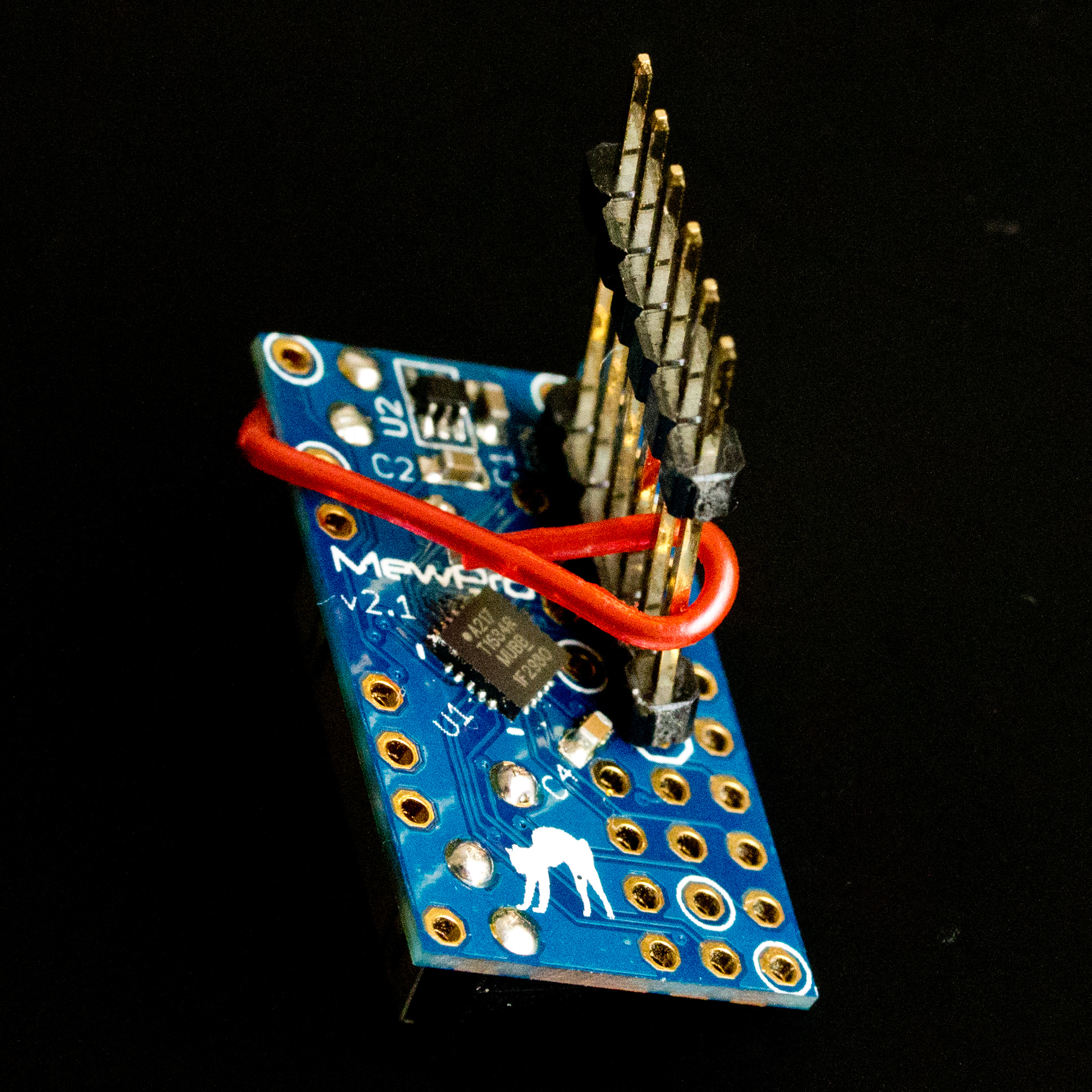
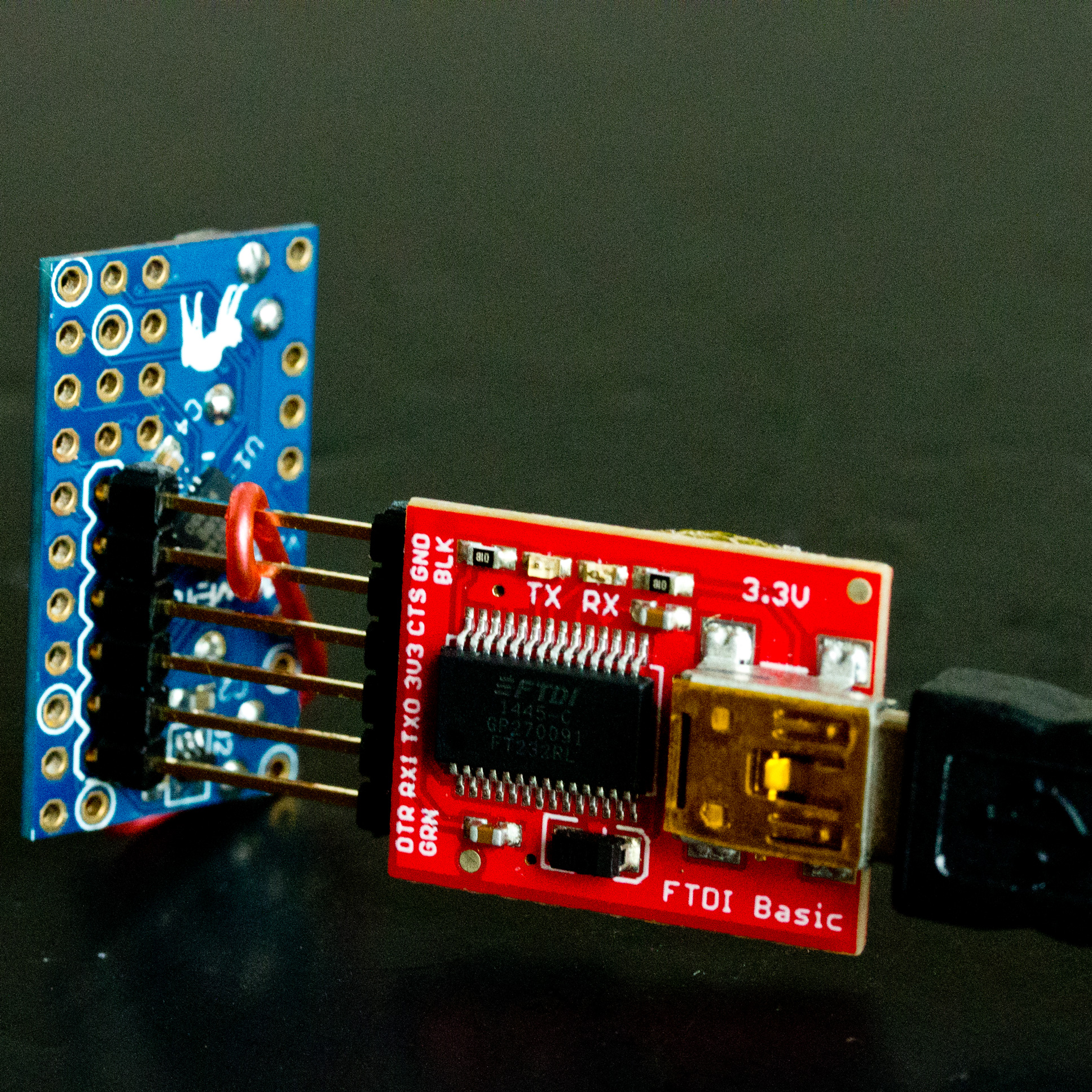
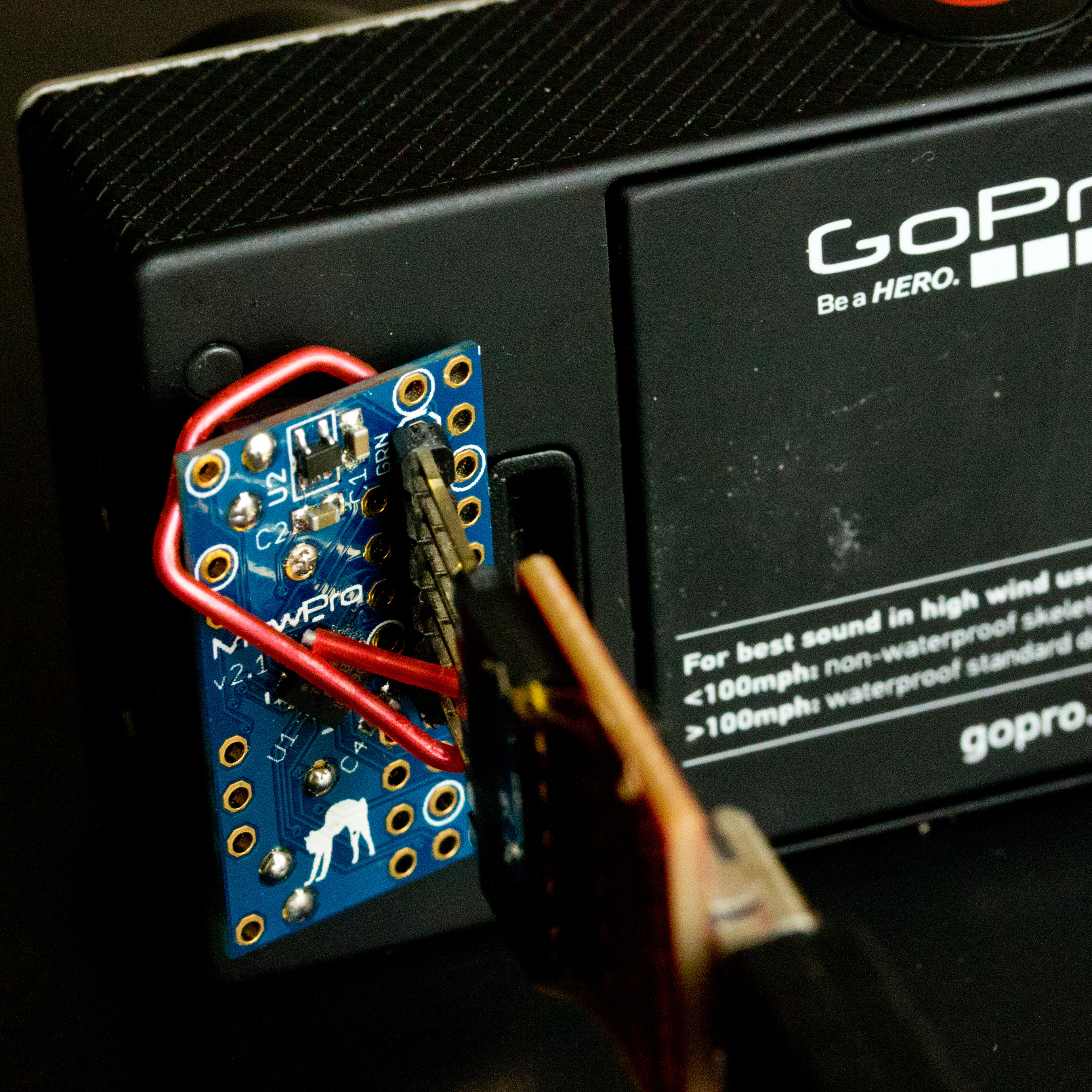
Connect MewPro 2
to your PC w/ FTDI board and the temporary header.
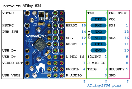
Connecting FTDI please refer the pinout image below:
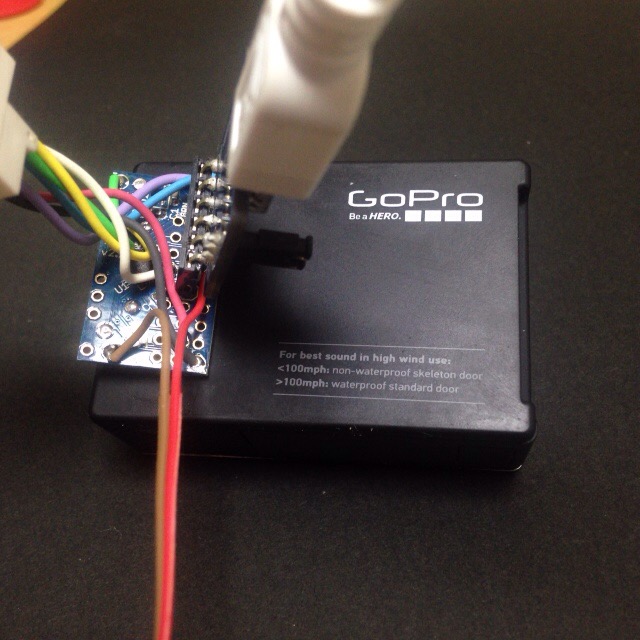
Then connect them to GoPro Hero 4 Black/Silver (The photo below is stolen from our old blog post and connecting to Hero 3+ Black, but I think you will understand where you should connect to. 🙂 ).
In Arduino IDE application, select [Tools]→[Board]→[ATTiny1634 (optiboot)] and [Tools]→[Port]→[(the port where you connected the FTDI cable)]. (B.O.D. and Clock settings are “don’t care” as these values are only effective when you burn a bootloader to the microcontroller by using an ISP programmer.)
The MewPro4 source code is originally targeted to users with multiple cameras, so for standalone usage please edit/change the following line in MewPro.h at line 8
...
// undef if MewPro 2 board is used as standalone
#define USE_GENLOCK
...
to
...
// undef if MewPro 2 board is used as standalone
#undef USE_GENLOCK
...
Now you are ready to compile/upload the source code. Click on “check mark” icon at the top left of Arduino IDE window compiles the code. And “Right arrow” icon at the right next uploads the compiled binary to MewPro 2 board.
If you like to use a time alarm function MewPro4 source code has such an example included. In this case you must download Time and TimeAlarms libraries from PJRC site, modify the line #undef USE_TIME_ALARMS in MewPro.h to #define USE_TIME_ALARMS, and also remove two comment-outs ‘//’ located at these two lines:
#include <TimeLib.h> // *** please comment out this line if USE_TIME_ALARMS is not defined ***
#include <TimeAlarms.h> // *** please comment out this line if USE_TIME_ALARMS is not defined ***
Then edit d_TimeAlarms.ino to set your alarms.
Controlling Standalone Hero 4 from Arduino Monitor
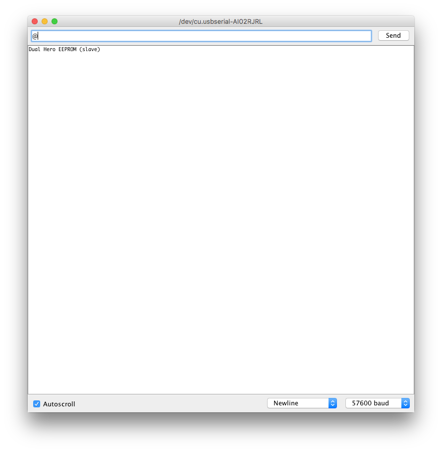
Open “Serial Monitor” in Arduino IDE window (click the the top right “magnifier” icon). Set [57600 baud] using the bottom right pulldown, [Newline] the middle pulldown, [Autoscroll] the left box checked.
Type ‘@‘ (one letter representing at sign) in the input area of Serial Monitor, and hit return key.
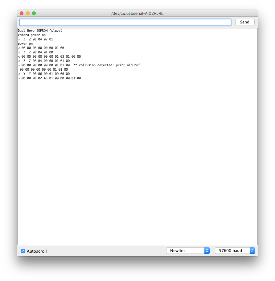
The message “camera power on” is shown and your GoPro Hero 4 turned its power on.
The messages on “Serial Monitor” shows communication details between Arduino and GoPro. And now you can type in any of I2C commands found in “List of GoPro Hero 4 I2C Commands“.
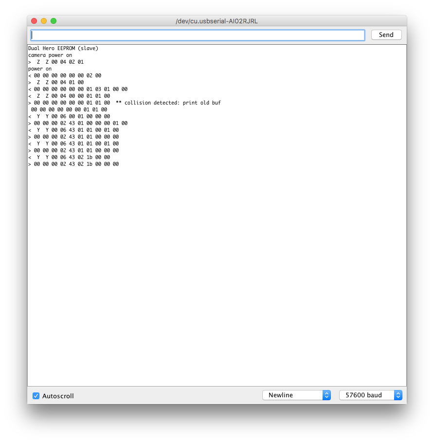
Try typing “YY000101000100” (change camera mode to video) and hit return key unless your camera is in video mode. Then type “YY00021B0000” (and hit return) and “YY00021C0000” (and hit return). (Start recording! Stop recording!!)
If you finished type “ZZ00030101” (and hit return). (This should power off your GoPro Hero 4.)