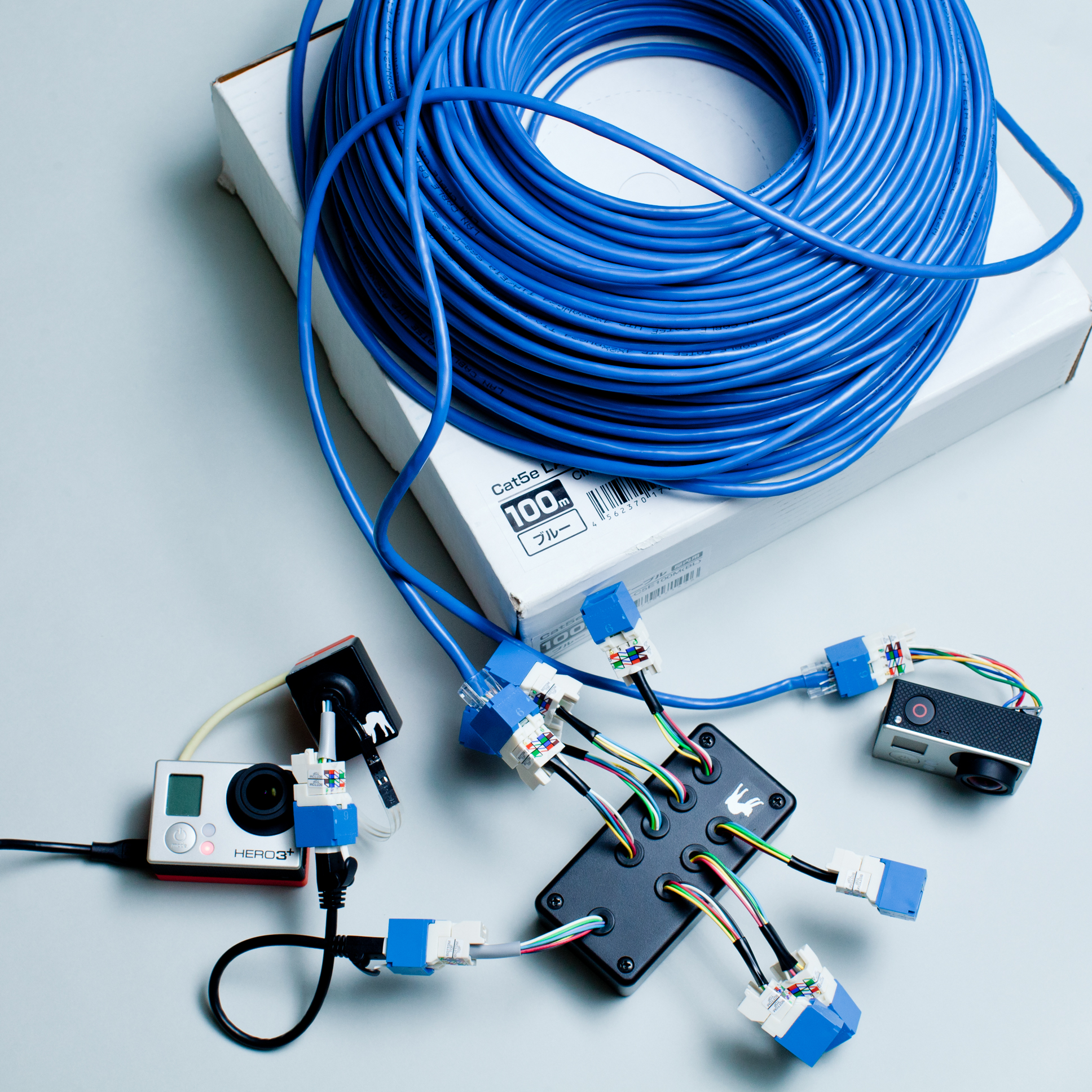
Using 100 meter Cat5e Ethernet cable, GoPro Hero 3+ Black and MewPro we succeeded in genlocking at long distance.
One of our best customers recently reported to us that Genlock Dongle + MewPro system didn’t work if cable length was very long.
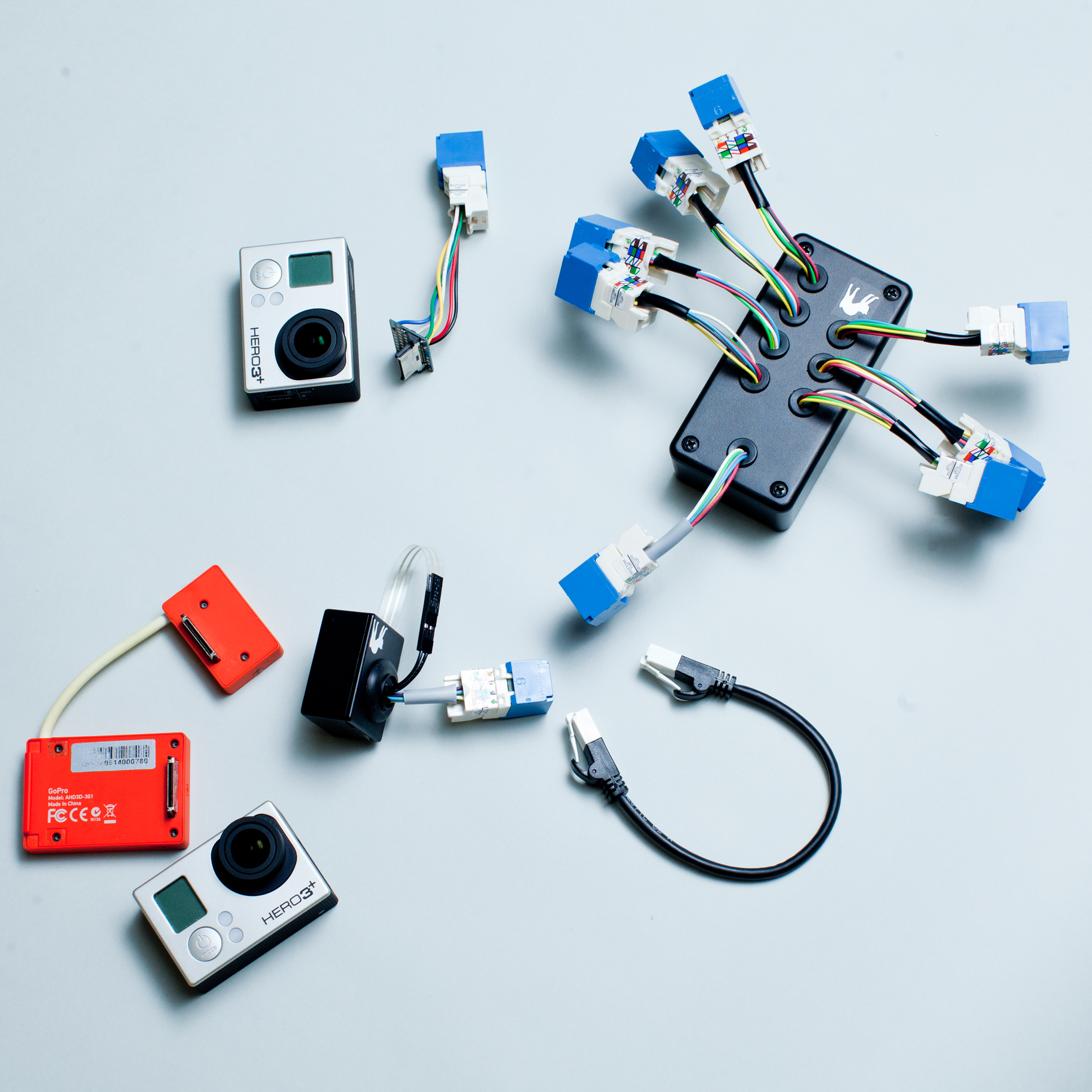
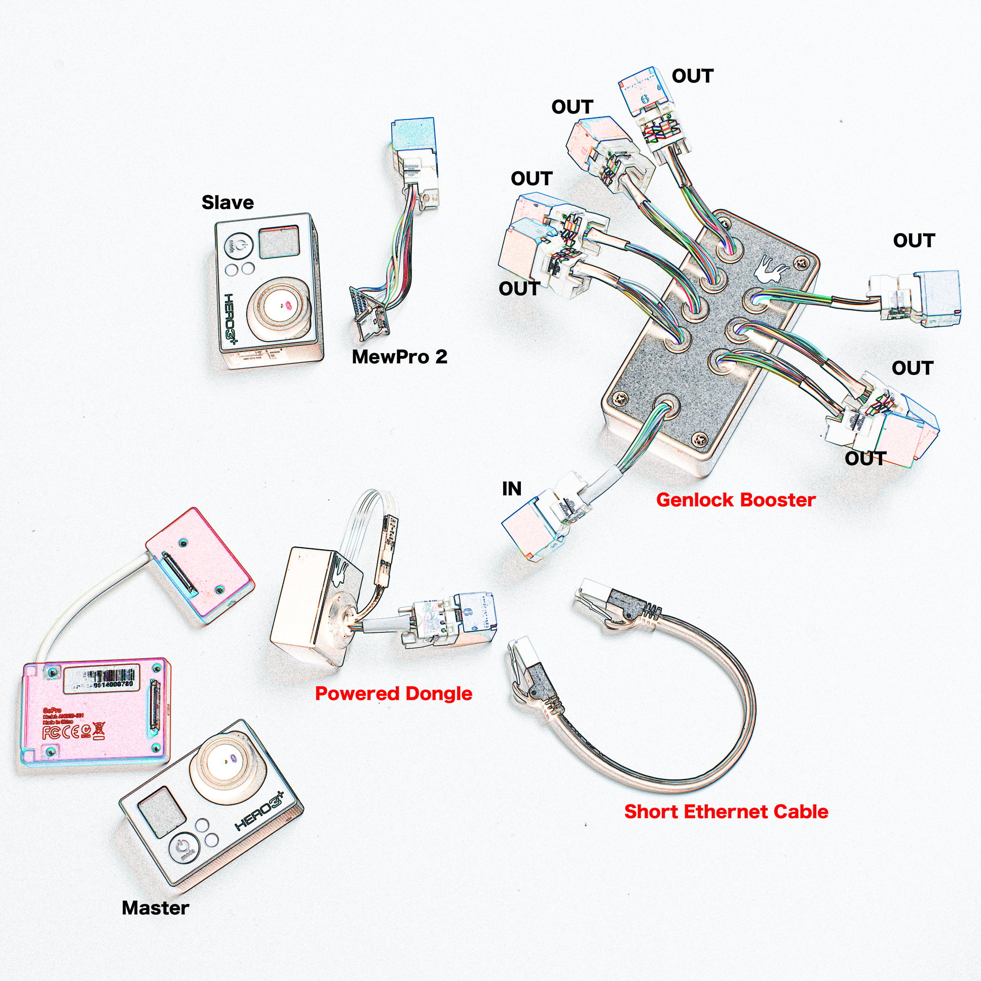
To overcome the issue we consider electrical isolation of long cables will suffice. We insert buffers (74HC4050 a hex non-inverting buffer) between the Genlock Dongle and each of the cables to MewPros, and voilà it works!
We made a Genlock Booster consisted of seven 74HC4050’s and enclosed in a box. The Genlock Booster is for use with eight cameras in single dongle configuration.
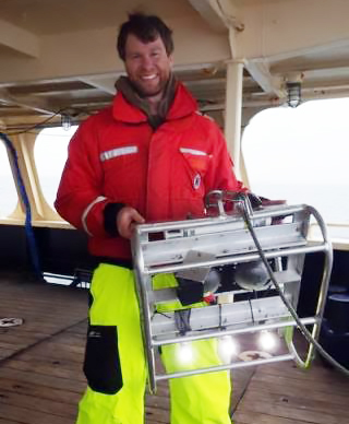
There’s a project in NOAA (National Oceanic and Atmospheric Administration) that uses our MewPro + Genlock system.
The researchers made a special housing for GoPro cameras and the system: It has bulkhead connectors for water-proof cables and these enables control of cameras from the ship.
The following video shows underwater of the Aleutian Islands, USA.
(Video and photo by courtesy of Mike Levine, Contractor to NOAA AFSC RACE)
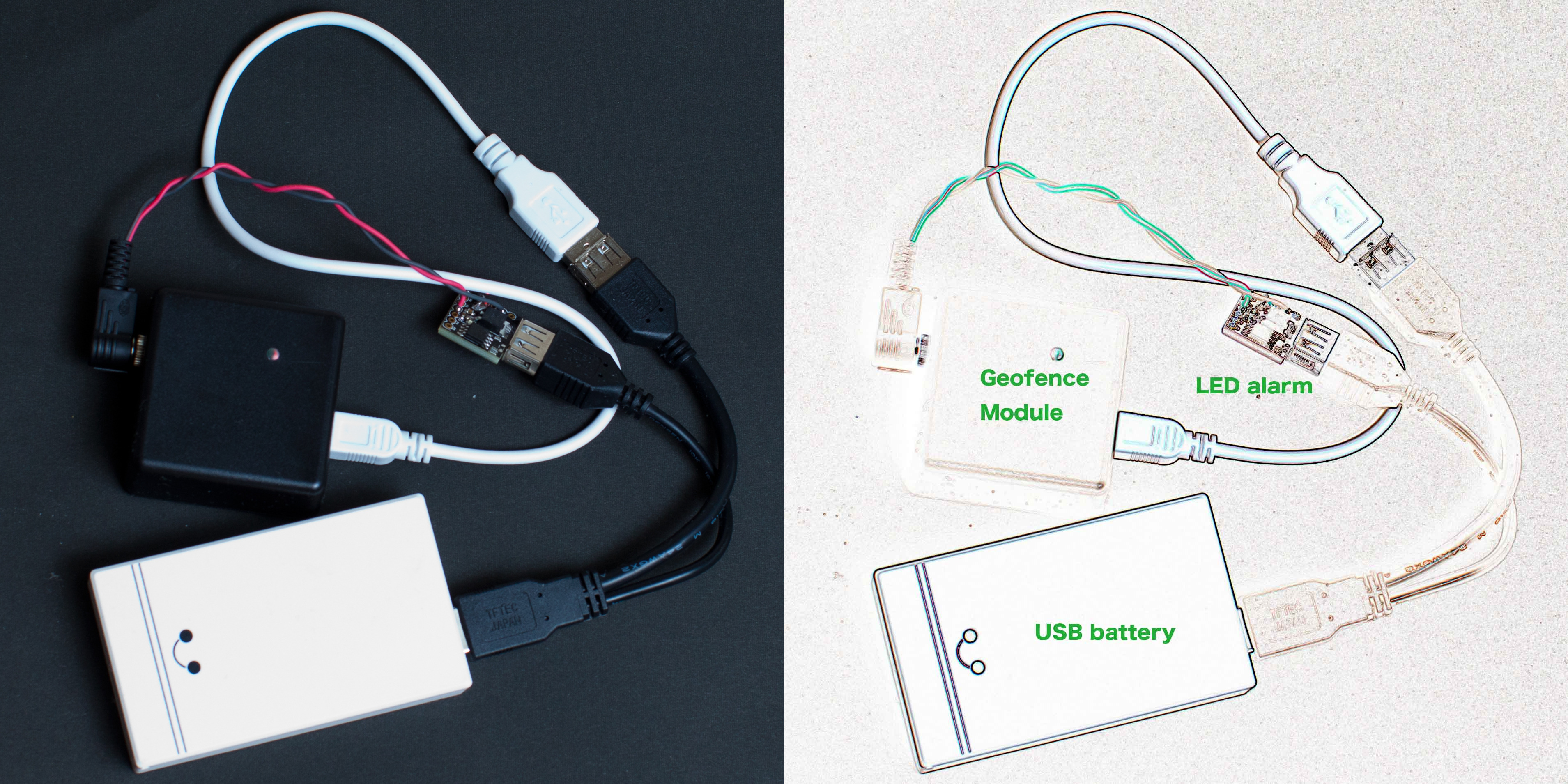
A DIY stand-alone unit for watching geofence breach is made by using Teensy 3. The general purpose device, which has a similar functionality of geofence or sending notification by location on smartphones, is also usable to automatically start/stop recordings of GoPro camera with aid of MewPro.
Details
Although each MewPro has a microcontroller (AVR) on its board, we decided to separately use Teensy 3 (Cortex-M4) that can do with double-precision floating-point (64 bits) numbers. Implementing geofence as stand-alone enables the unit to control not only GoPro cameras but also other equipments (such as LEDs and buzzers) with regard to preconfigured geofence, which can be a union of convex polygons.
Connect to LED to Test Geofence Function
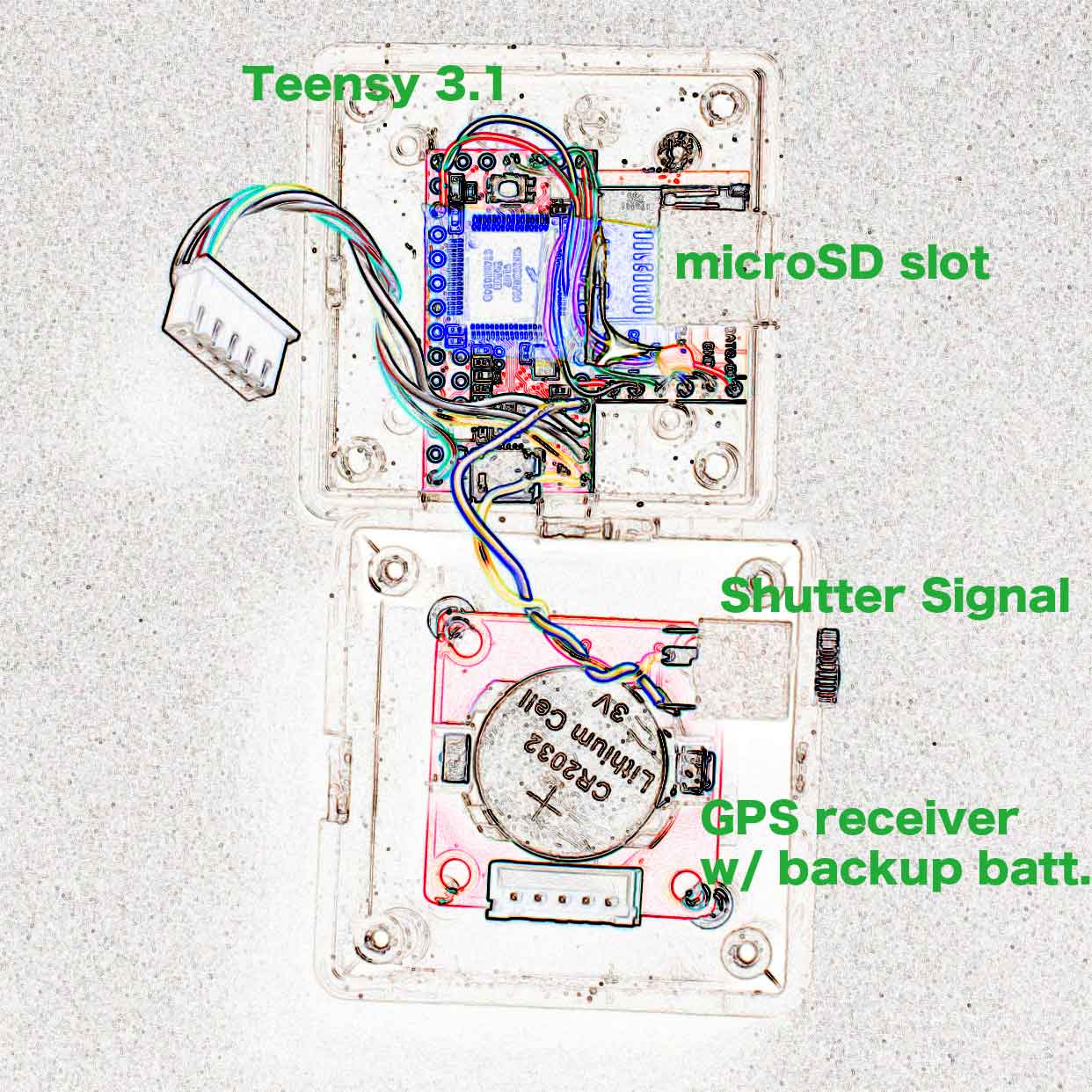
To test the unit we connect an LED to its alarm pin: SHUTTER signal (red wire) at the audio mini plug in the photo becomes LOW/hi-Z if it enters/exits the geofenced area. We use digistump’s ATtiny85 Digispark board to watch the pin and to turn on/off the LED, however, you can use any device such as GoPro+MewPro or something as Digispark.
The following is a teardown of the DIY unit.
Resources
The module is an open software/hardware. The schematics and the source code with a simple README document are downloadable from:
By syncing GoPros and utilizing GPS it is demonstrated how to accurately measure time of an observed event.
For example, taking astronomical videos or photos it is usually important to record the time when those captures were made. Both professional and amateur astronomers interested in especially eclipses or occultations, such as the Moon passes in front of a star, have ever invented many kind of timekeeping devices for this purpose. Needless to say the more exact, the more preferable.
The post proposes a new convenient method to keep time whose precision is within several milliseconds or the duration of one video frame.
The idea is based on the following facts:
Any number of GoPro cameras can be genlocked or in sync by every frame and scan line to a timing generator.
Some GPS receiver can output a pulse-per-second (1PPS) signal that have an accuracy of nanoseconds.
Unfortunately we cannot synchronize these two signals, the ones from the genlocking source and the 1PPS. However, we can easily record both of them together by visualizing the latter using LED and pointing one of all cameras in sync with the former to the LED.
In the rest of the post we will perform an experiment to confirm that the precision is kept within one frame while capturing videos.
Measurement
To assure perfectness of the sync we use the following equipments:
Microcontroller boards, OLED (Organic Light-Emitting Diodes) character displays and LEDs
These are required for displaying GPS time in a form of hh:mm:ss (hh=hour, mm=minute, ss=second) and every zero second.
MacBook Air
To show the NTP Internet time for intuitive reference.
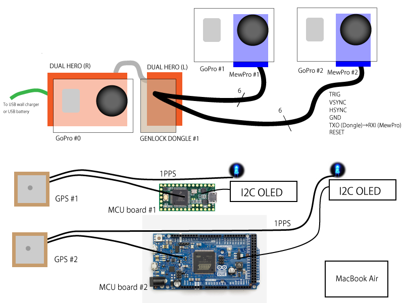
Block diagram of measurement equipments
We use three cameras in sync: Two cameras are pointed to LEDs and OLED character displays (another camera is to control the two). Two GPS receivers are of different brands: Each 1PPS signal is aligned to UTC and visualized as hh:mm:ss on the OLED display, and lights the LED when asserted.
Doing this requires some microcontrollers between the GPS receivers and the I2C OLED character displays we use Teensy 3.1 and Arduino Due boards. And in order to make sure that our programs running on these doesn’t have any bugs we also prepare a MacBook Air to show the Internet time that is obtained from an NTP server.
Results and Discussion
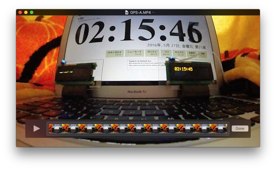
The following are clipped from the videos (WVGA, 240fps) shot by the two of genlocked cameras:
(One frame before 2016-05-27T02:15:46.000Z. Up: View from the right. Bottom: View from the left.)
The blue LEDs haven’t lit yet (cf. the next two images). The MacBook Air behind is slowly changing its time display from 02:15:45 to 02:15:46, however, it turns out to be not so accurate as 1PPS time. The right OLED display shows nothing: This means the OLED, which is always blinking in order to reduce power consumption, is in an off period. At the same time the left is on the way to refresh 02:15:45.
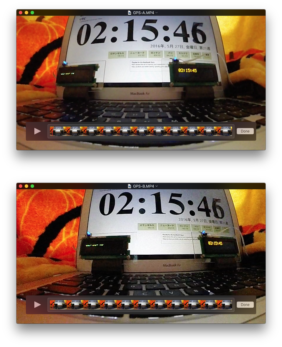
Each of above frames is followed by the next, respectively:
(Exactly it is 2016-05-27T02:15:46.000Z. Up: View from the right. Bottom: View from the left.)
Both of the blue LEDs light. The right OLED display shows the time as 02:15:45. According to GPS’ protocol (aka NMEA) specifications, a rising edge of 1PPS signal occurs on an exact zero second, which is followed by a GPZDA statement aligned to UTC. In the current system the blue LED lights when 1PPS is asserted, and OLED is rewritten when a GPZDA is received by the microcontroller. So it is no wonder that our OLED is not updated yet this time. The left OLED is on its way to erase 02:15:45.
These four images proved the exactness of sync among not only the cameras but also the GPS receivers. And we confirmed the system could be utilized for exact time measurements of events.
Reference
The above stills are extracted from the following unmodified original movies (MP4 files):