

MewPro Iliad generates HSYNC/VSYNC and synchronizes any number of GoPro Hero 4 Blacks or Silvers. The post describes details of this new genlock device.
How Iliad Works
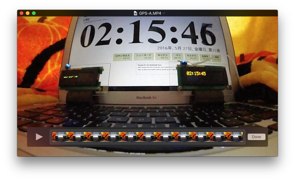
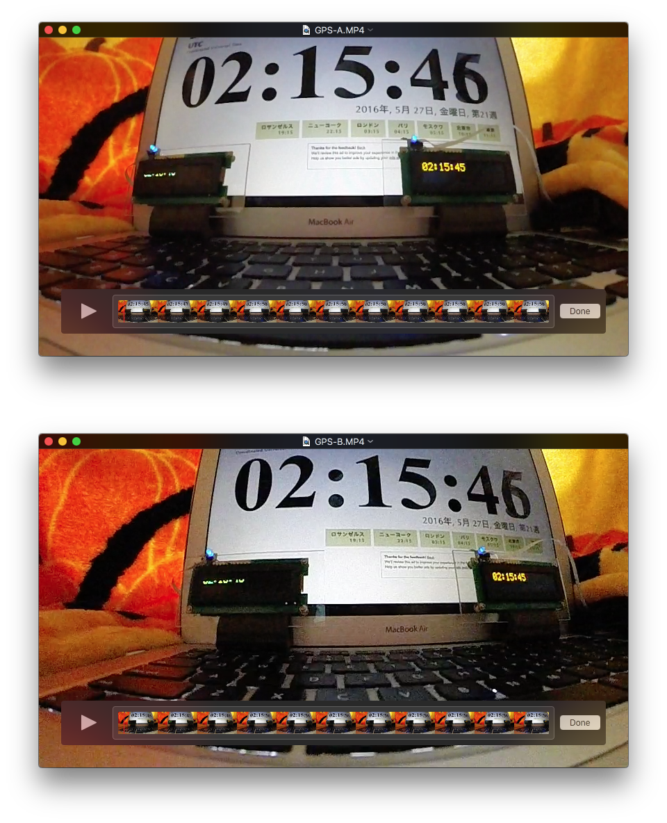
The following clip is a demo of MewPro Iliad, the production version of our sync generator/controller for Hero 4 Black/Silver.
Iliad can be interacted with any IR remote by learning its code and/or with three on-board momentary switches, which correspond to the familiar Mode/Shutter/Setting buttons of GoPro Hero 4 Blacks. In the short footage above three cameras are in complete sync: Power on – sync setting – change video resolution/protune on – start recording – stop recording – change to camera mode – shoot photo – power off.
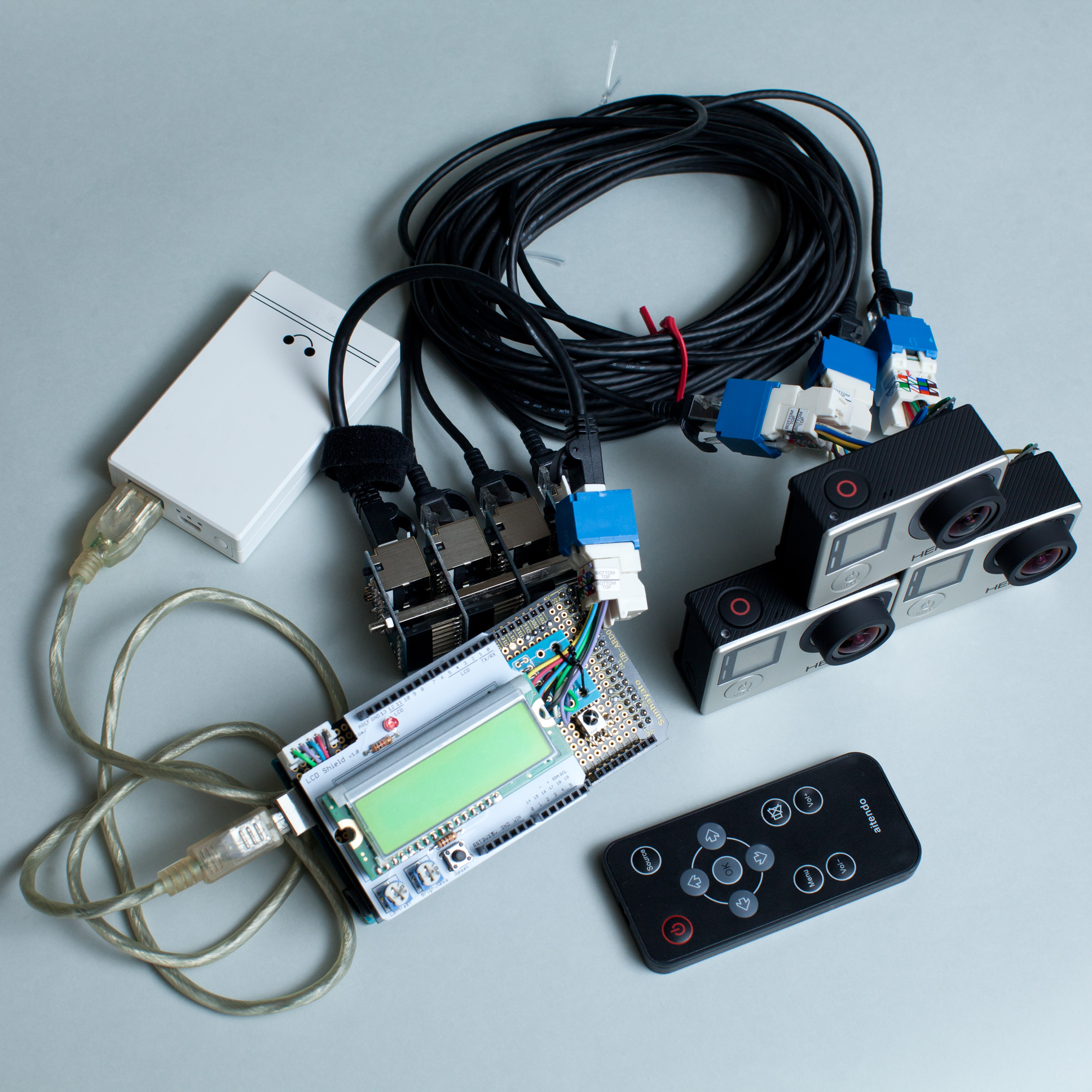
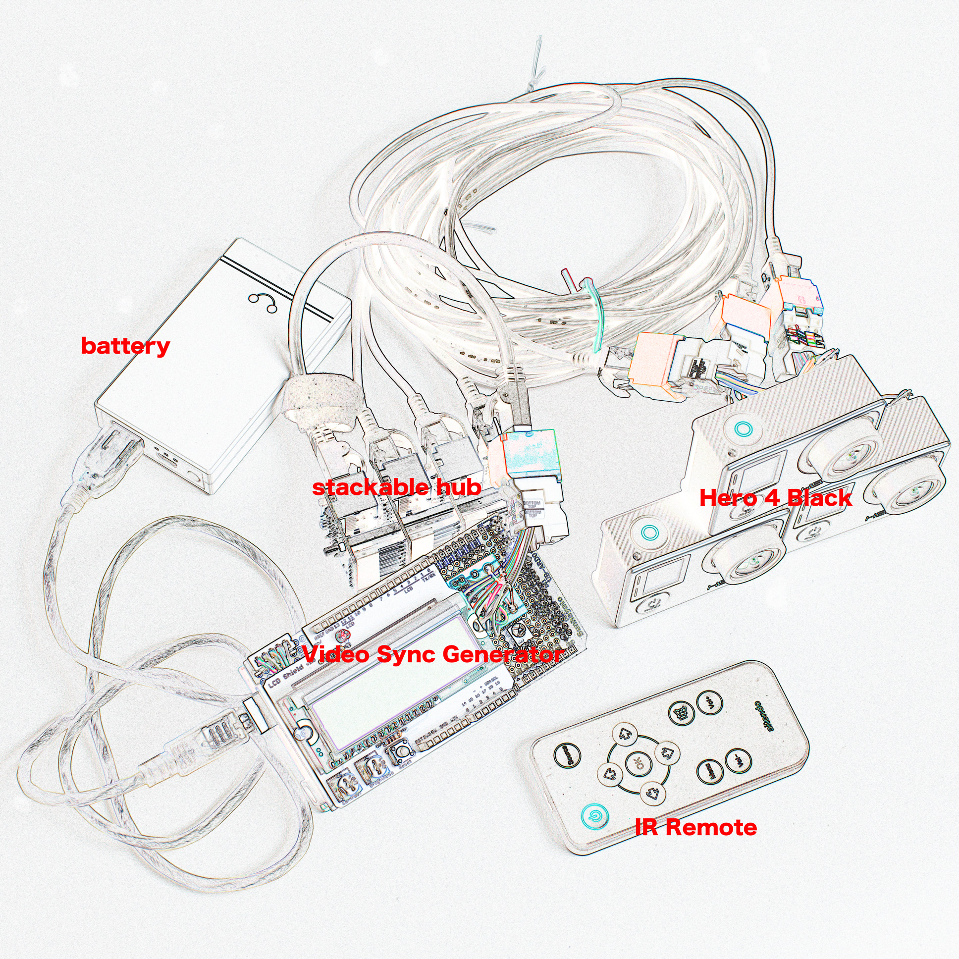
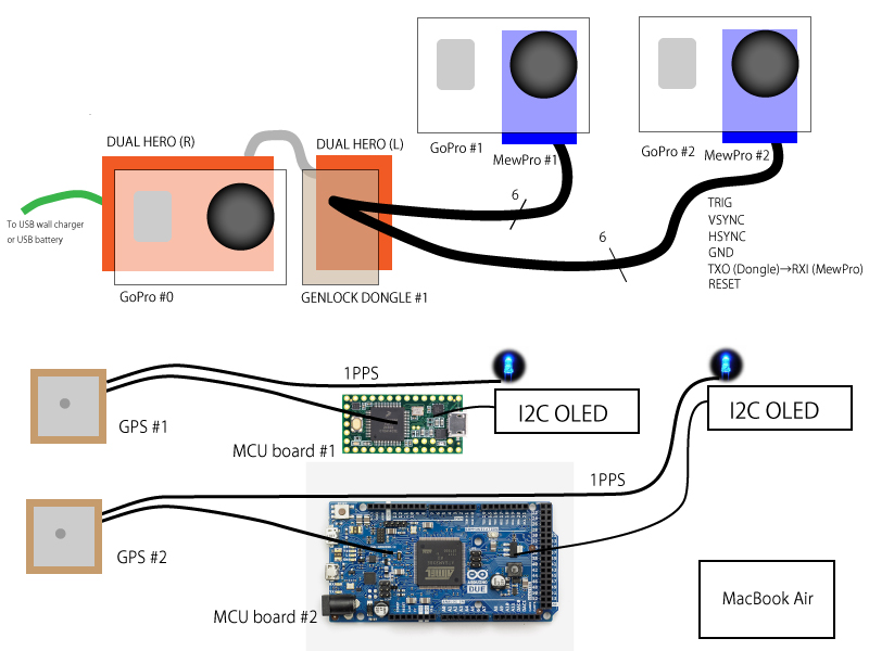
To make the demo we used the following items:
| qty | |
|---|---|
| GoPro Hero 4 Black | n |
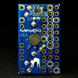
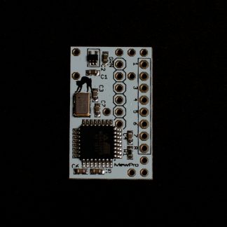
| MewPro 2 * | n |
| MewPro Iliad * | 1 | RJ45 Stackable Hub with Buffer * | for input: 1, for output: n |
| USB wall charger | 1 |
| Cables and wires |
(Note: n is the number of cameras. In our case n=3.)
The items marked * are in our shop.
Currently MewPro Iliad is still in beta stage, however, here we venture to sell it because there is huge urgent demand. It can do the following.
- Video: All the video modes Hero 4 Black/Silver supports
- Photo: Single shot in any resolutions
The camera has many charming submodes such as “Timelapse” or “Night Lapse” or “Burst” or something but shooting in these submodes is not genlocked. This might be due to camera’s restrictions so please don’t blame MewPro and Iliad.
GoPro Hero 4 Black/Silver’s firmware can be version 03.00.00 or later (N.B. The version is shown on camera’s LCD without the last two digits as “03.00” at camera power on).
Note: There is a fatal bug in version 04.00.00 or later that causes bulk setting sync transfer impossible, i.e., settings cannot be synced when power on. Thus, we strongly recommend to use MewPro Iliad with the firmware version 03.00.00. And if you have version 26.01.10 for Omni then it also works after sending a command to MewPro board, however, in this case only two video modes (2.7K 4:3 30/25 and 1440 4:3 60/50 (NTSC/PAL)) are supported and there is no reliability improvement at all.
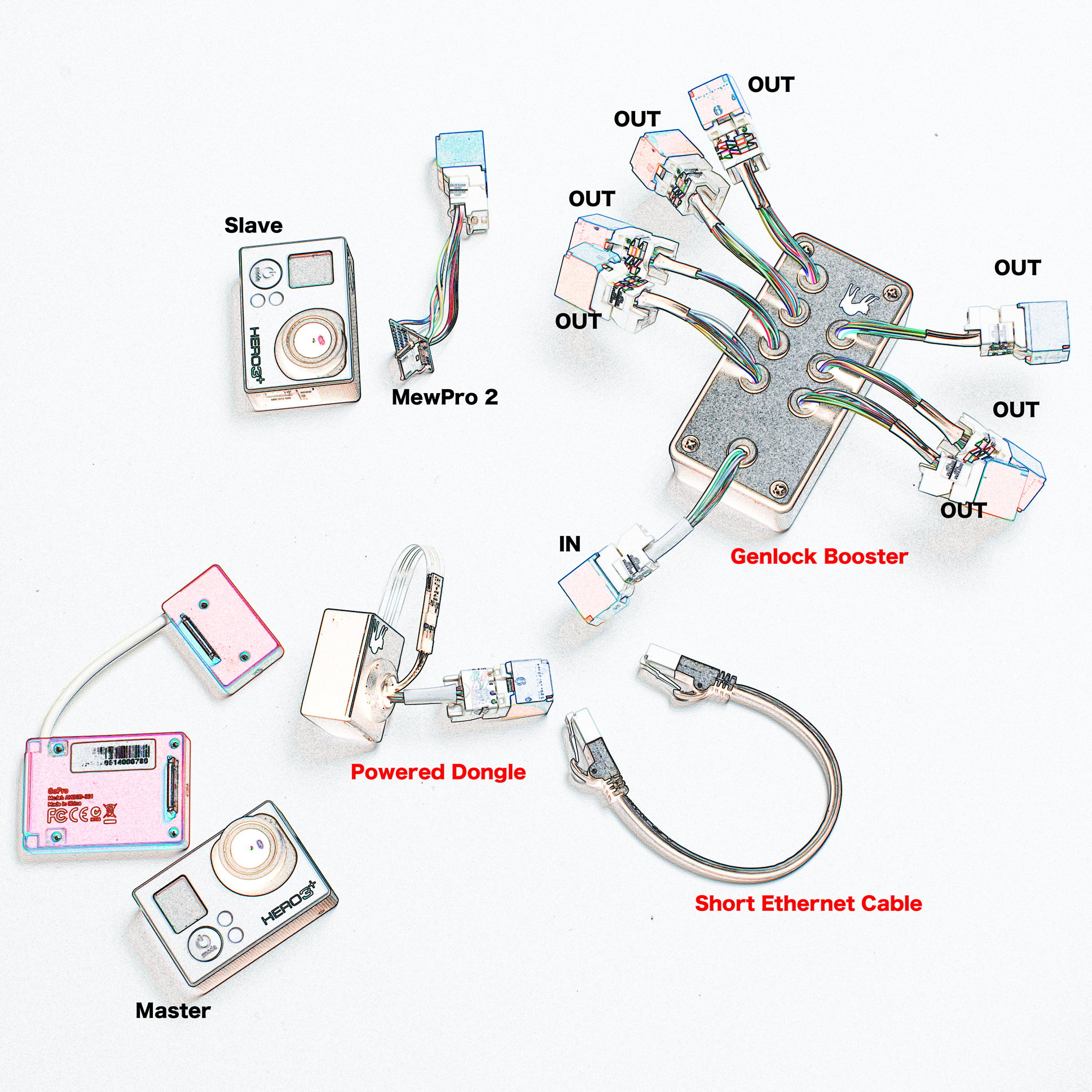
Connections
MewPro Iliad and MewPro2’s can be connected by using 6-core cables or (straight) ethernet cables of any category.
Case 1: Using 6-core cables
On the Iliad board there are thru holes for necessary signals.
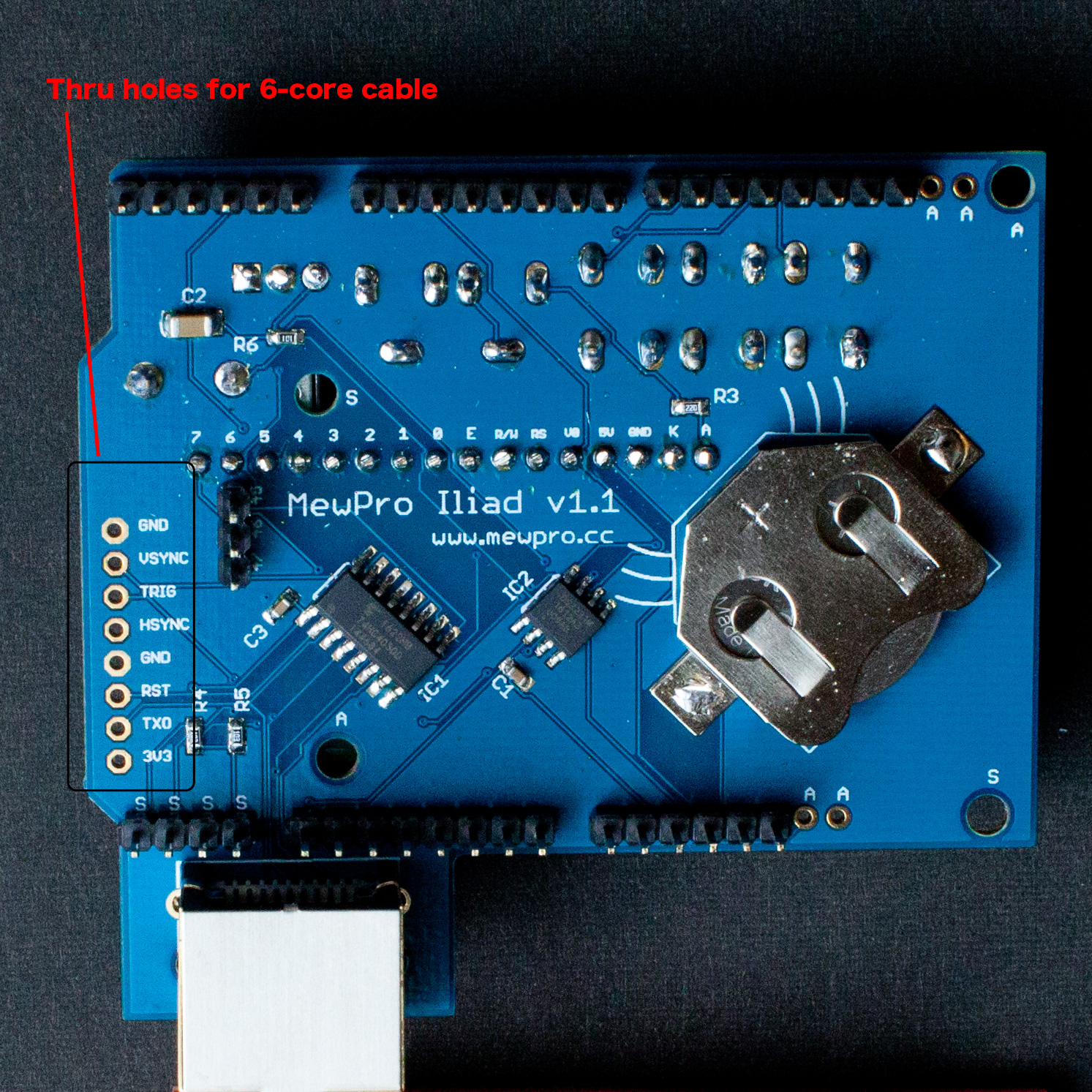
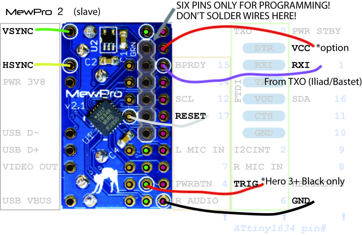
Connect 5 signals and optional 1 line to each MewPro 2 board as follows:
| Iliad | MewPro 2 | ||
|---|---|---|---|
| GND | — | GND | (*) |
| VSYNC | — | VSYNC | |
| TRIG | (no connection) | ||
| HSYNC | — | HSYNC | |
| RESET | — | RESET | |
| TXO | — | RXI (**) | |
| 3V3 | — | VCC | optional (***) |
Remark *: There are two GND pins on the Iliad board. It doesn’t matter you connect both or either of them.
Remark **: On MewPro 2 board there are two different RXI pins “FTDI RXI” and “RXI 1”. The former pin at the row “FTDI” is ONLY FOR PROGRAMMING. So you should connect the serial line from Iliad/Bastet to the “RXI 1” pin at the edge.
Remark ***: If you like to use Hero 4 camera without battery and feed 5V power thru side USB socket or VUSB pin on MewPro 2 board then also connect this line in order to feed power to MewPro 2 board from Iliad.
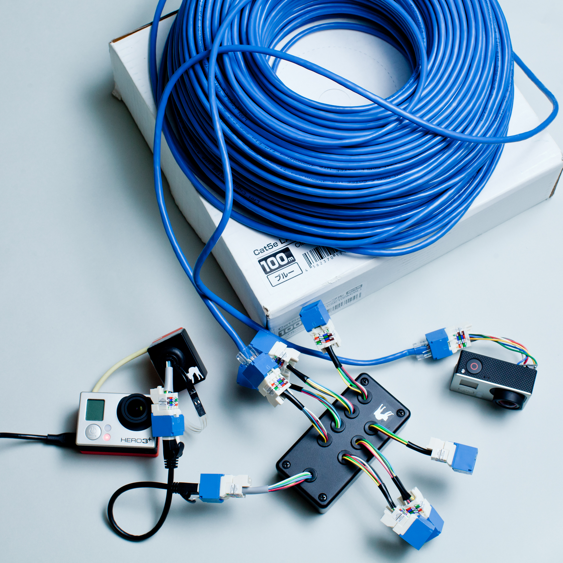
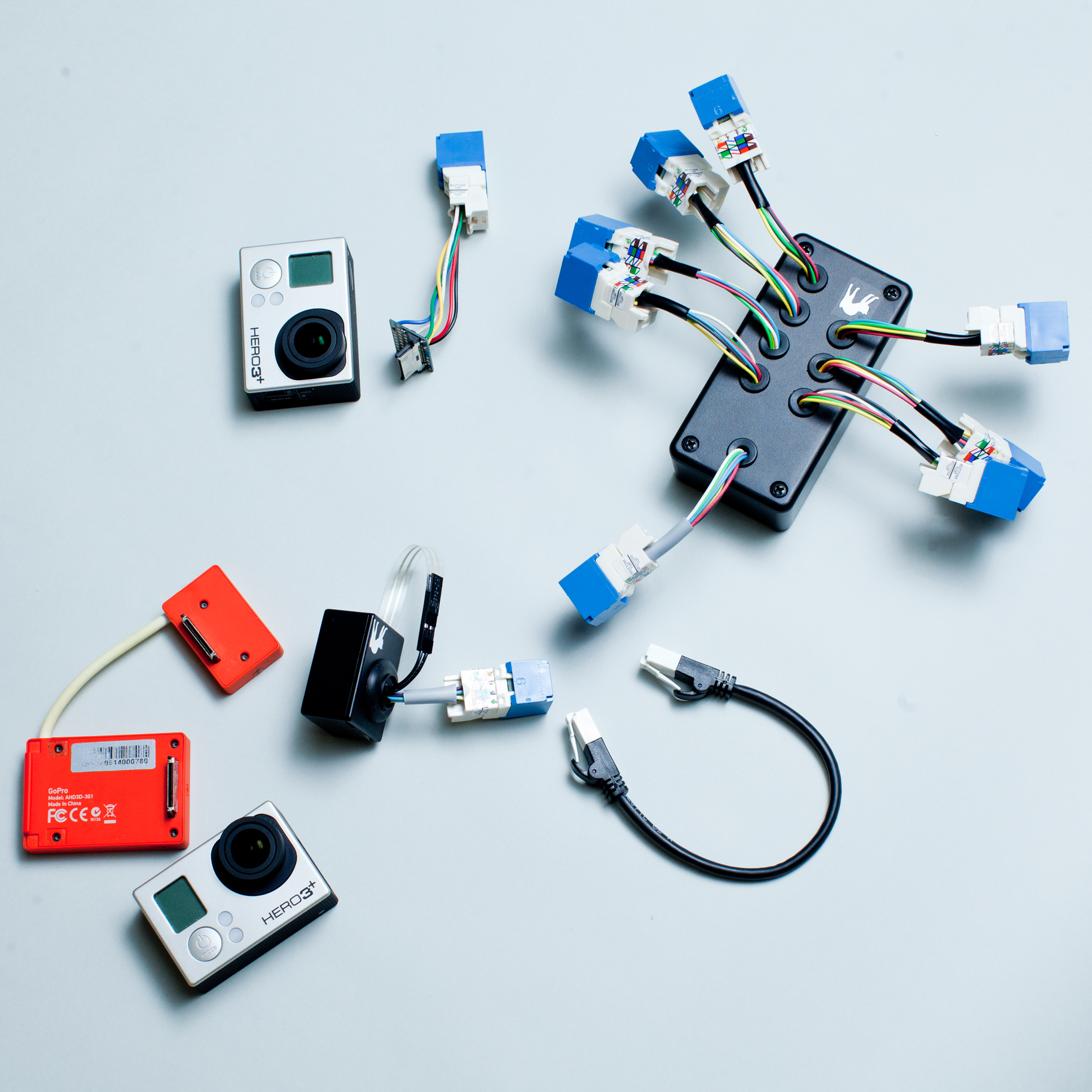
Case 2: Using ethernet cables
The Iliad board has a RJ45 receptacle to connect to an ethernet cable of any category. You can directly connect this to one or more MewPro 2 boards by simply branching each of signals.
Signals at the RJ45 receptacle of the Iliad board are:
| pin # | T-568A color | T-568B color | signal |
|---|---|---|---|
| 1 | white/green | white/orange | (no connection) |
| 2 | green | orange | VSYNC |
| 3 | white/orange | white/green | (no connection. reserved for TRIG) |
| 4 | blue | blue | HSYNC |
| 5 | white/blue | white/blue | GND |
| 6 | orange | green | RESET |
| 7 | white/brown | white/brown | TXO (Iliad) / RXI (MewPro 2) |
| 8 | brown | brown | 3V3 |
If you also bought RJ45 Stackable Hub with Buffer from our shop then all RJ45 connector pins are aligned as in Table 2.
Softwares
The software is being developed by using Arduino IDE that is downloadable from https://www.arduino.cc/en/Main/Software. If you are not familiar with Arduino platform there are many introductions or tutorials on the Net. So please refer them first.
If you bought Iliad from our shop then all the software is pre-installed. However, there will be frequent updates or bug fixes from us you’d better prepare the IDE.
Software for MewPro 2
Source code for Hero 4 Black/Silver is downloadable as a zip file from here:
https://github.com/orangkucing/MewPro4
To compile/upload please refer the README.md included in the zip file.
Software for MewPro Iliad
The Iliad board is designed as a shield of Seeed Studio’s Seeeduino Mega, which is an Arduino Mega 2560’s enhanced clone. You can use the Iliad board with the original Arduino Mega 2560 R3, however, the size will be larger. This is the reason why we ship MewPro Iliad with Seeeduino Mega.
Seeeduino Mega can run in either 5V or 3.3V logic. Iliad shield itself has a voltage translator so you can set Seeeduino Mega’s voltage, for which there’s a slide switch, to either voltage. However, according to Atmel’s ATmega2560 documentation 16MHz is “overclocking” when 3.3V so we recommend to use the board in 5V logic.
Source code for sync generator is downloadable as a zip file from here:
https://github.com/orangkucing/MewPro_Iliad
The code requires the following two external libraries to compile:
(Note: The IRremote library conflicts with RobotIRremote library in the standard Arduino IDE. So please delete
your_IDE_folder/Contents/Java/libraries/RobotIRremote
if you encounter some issues.)
To compile/upload is easier than MewPro4 application because it is nothing but an Arduino Mega 2560 clone. So please search the net for tutorial for it if you need.
Let’s Sync!
Everything is ready if you’ve done the above steps (If you bought all the items from our shop then installing software is not necessary).
Iliad board needs one CR2032 button battery to keep date and time. There’s a holder for it at the back of the shield. Please take care + (plus) side is the far side from the board (there’s a curved + mark both on cell and holder). The battery is expected to last two or three years.
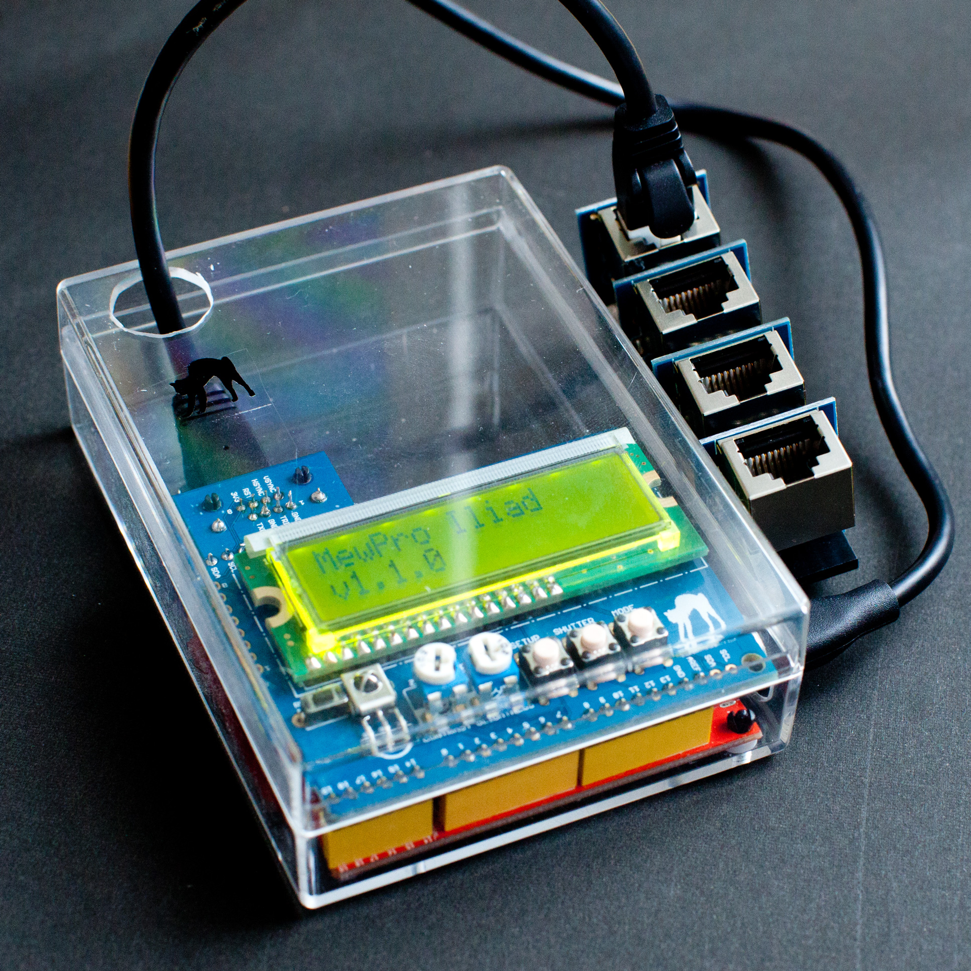
Connect USB cable between USB battery (or wall charger) and Seeeduino Mega with Iliad. LCD should light and show “MewPro Iliad” and its software version. If it doesn’t show anything then please try to turn the potentiometer marked 103 for contrast or 102 for brightness.
After the start up message “MewPro Iliad” is shown, you can use it as if it were a real GoPro Hero 4 Black. Camera’s side button for setup corresponds to the SETUP momentary switch, shutter to SHUTTER, and mode to MODE.
(Note: To power on all the camera long press MODE as well as to power off.)
Furthermore, there’s an extra menu that real camera doesn’t have. You can enter to the menu by pressing SETUP while the start up message is shown. The extra settings consist of:
- Date/Time – Setting date/time to on-board real time clock chip
- Reset – Reset Iliad to factory default
- Mount microSD – Resetting all the MewPro 2 board
- Learn IR code
By using the last menu item Iliad can learn any IR remote’s code (from TV remote or Video remote etc.) so you can control GoPros with your favorite IR remote controller.
Also resetting all the MewPro 2 board has the same effect to detaching all the MewPro 2 from cameras. This is usually very convenient if you fix up all the cameras in a rig.
Enjoy!